G 85 Technical Data
wc_td000214gb.fm 121
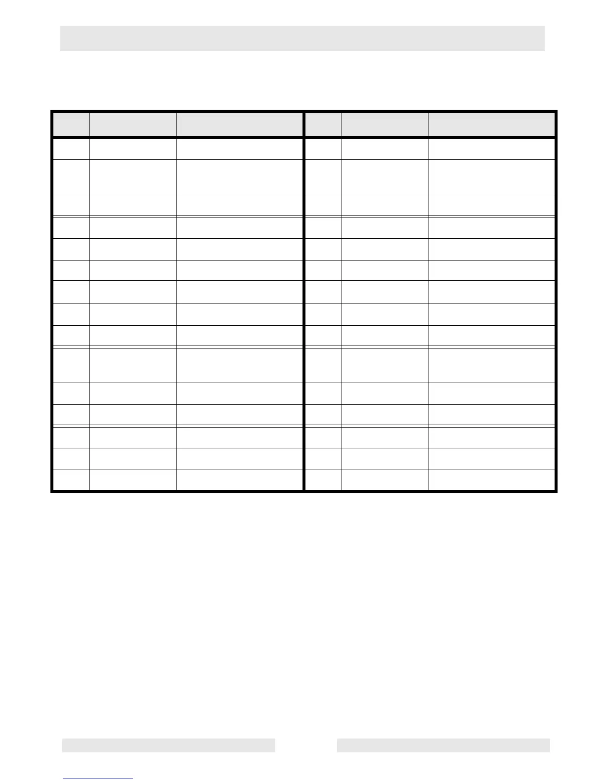
10.7 ECU Harness Connector
See Graphic: wc_gr002817
Ref. Wire Color/# Destination Ref. Wire Color/# Destination
A1 --- --- F1 Green/905 CAN bus
A2 Red/012C Harness Connector
(HC) terminal G
F2 --- ---
A3 Orange/493 Fuel control solenoid F3 Violet/467 Oil pressure sensor
B1 Brown/461 Colant temp sensor G1 Yellow/904 CAN bus
B2 Violet/447 Engine crank sensor G2 W/L / 474 ECM
B3 Gray/918 HC terminal N (N/A) G3 Orange/473 HC terminal H (N/A)
C1 Violet/947 HC terminal R (N/A) H1 --- ---
C2 --- --- H2 --- ---
C3 Gray/428 Fuel temp sensor H3 --- ---
D1 Orange/463 Manifold Air Temp
(MAT) sensor
J1 Gray/418 N/A
D2 Gray/448 Engine crank sensor J2 Black/050C Ground
D3 Yellow/914C Sensor return J3 --- ---
E1 --- --- K1 Red/022 10A fuse
E2 Brown/911C Sensor excitation 5V K2 Brown/491 Fuel control solenoid
E3 White/439 HC terminal K (N/A) K3 White/429 Air heater relay
 Loading...