Mobile Generator John Deere Engines With ECU
wc_tx000698gb.fm 59
6 John Deere Engines With ECU
6.1 John Deere Engines With ECU Background
The Tier II John Deere engines with electronic control systems are
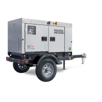
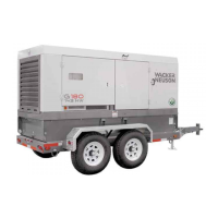
used on Wacker Neuson generator models G 85, G 125, and G 160.
The electronic control system consists of:
• Engine Control Unit (ECU); the computer which controls fuel, and
the ignition system.
• The following sensors: oil pressure, coolant temperature, fuel
temperature, manifold air temperature, crank position and speed.
• Fuel pump control solenoid.
• Manifold air heater.
The electronic control system serves as a governor by controlling the
fuel to the engine. It does so by controlling the engine’s injection pump
control valve through a proportional solenoid. In doing so, fuel is
delivered according to engine conditions, in precise amounts, and at
the precise time in relation to piston position.
The ECU communicates with the Engine Control Module (ECM)
mounted to the generator’s control panel through a Controller Area
Network (CAN). The wiring between the controllers forms a bus
(physical electrical interface where many devices share the same
electrical connections). Diagnostic tools available from John Deere
can plug into the CAN bus to assist in troubleshooting the operation of
the engine. The ECM controls the engine up through engine start
(cranking). Once started, the ECU controls the running of the engine.
The ECU has diagnostic abilities and shares engine diagnostic
information through codes which are displayed on the ECM display
screen. These diagnostic codes are referred to as “SPN/FMI” codes:
Suspect Parameter Number (SPN) and Failure Mode Identifier (FMI).
SPN/FMI codes are conveyed in a two-part code number. The SPN
typically contains between two and four digits and is the first number
of the code. The FMI contains one or two digits and is the second
number of the code. For example, if the ECM displays “SPN/FMI 100.
4”, The SPN “100” indicates a condition with the engine oil. FMI “4”
indicates that the engine oil pressure input voltage is lower than the
sensor’s specification—a condition associated with a disconnected oil
pressure sensor. There are many such SPN/FMI codes. See the John
Deere service manual for more information

 Loading...
