G 85 Technical Data
wc_td000214gb.fm 123
See Graphic: wc_gr004692
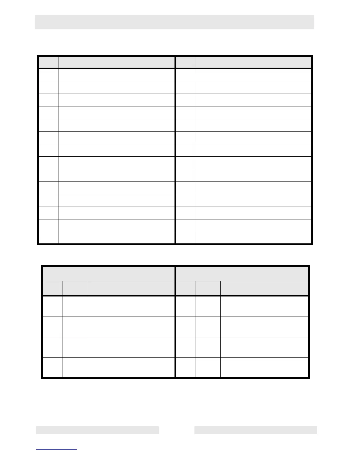
Ref. Description Ref. Description
1 Lug door (safety interlock) switch 15 Voltage Selector Switch (VSS)
2 Mechanical lugs 16 Generator
3 Plug 3 - current transformer inputs 17 Automatic Voltage Regulator (AVR)
4 Plug 4 - line voltage inputs 18 Voltage adjustment rheostat
5 Shunt 19 Terminal block
6 120V 20A GFI receptacle 20 Exciter rotor windings
7 120V breaker 21 Exciter stator winding
8 240V 50A breaker 22 Rotor
9 240V 30A breaker 23 Rectifier (diodes)
10 240V 50A receptacle 24 Main rotor winding
11 240V 30A receptacle 25 Main stator windings
12 Engine Control Module (ECM) 26 Auxiliary winding
13 Bus bar 27 Stator
14 Main breaker 28 Terminal strip
ECM Plug 3 Wires ECM Plug 4 Wires
Pin Wire Description Pin Wire Description
4Or
39
Ammeter line input CT3 3 Or
41
Voltage line input L3 at volt
selector #28
1W
36
Ammeter input CT com-
mon
4Y
43
Voltage line input L2 at volt
selector #20
5Y
38
Ammeter line input CT2 2 Br
42
Voltage line input L1 at volt
selector #3
2Br
37
Ammeter line input CT1 - - ---
 Loading...