Tables
Fuses
190
BA RD24_RD27 en 04
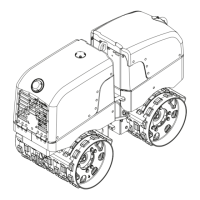
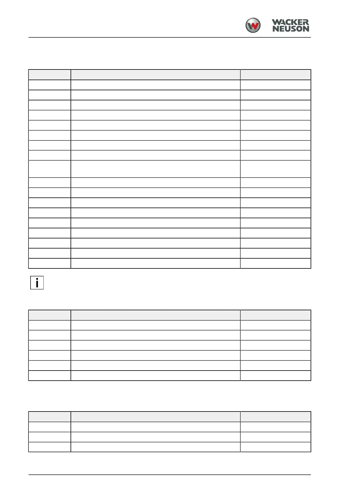
5.03.02 Steering column
[3] Central electrical system
Position Fuse assignment Fuse
F1 All-wheel lock 5 A
F2 Time relay cold start assistance 1 A
F3 Drum edge lighting 15 A
F4 Driving light, left 10 A
F5 Driving light, right 10 A
F6 Reversing lights 15 A
F7 Working spotlight 15 A
F8 Pilot light cold start assistance 5 A
F9 Edge pressing and cutting assembly (KAG), switching between
left-hand and right-hand side
5 A
F10 Pedal switch sprinkling 15 A
F11 Pedal switch additive sprinkling, seat heating 15 A
F12 WIFMS Gateway 10 A
F13 Socket 15 A
F14 Signal horn 15 A
F15 Additive sprinkling pump 15 A
F16 Water sprinkling pump 15 A
F17 Rotary beacon 15 A
FT Plug-in socket for fuse test
NOTE
You can use the fusible test receptacle to check a fuse.
The green light-emitted diode (LED) lights up when the fuse is functional.
[4] Central electrical system/options 2
Position Fuse assignment Fuse
F18 Reversing alarm 15 A
F19 Fuel pump, generator 7.5 A
F20 TCU (terminal 15) 7.5 A
F21 TCU (terminal 30) 7.5 A
F41 Diagnostic interface WIDIAG 7.5 A
F42 Seat belt buckle monitoring device 5 A
5.03.03 Dashboard/control panel
[5] Options 3
Position Fuse assignment Fuse
F40 HCM, HTM 7.5 A
F401 Track Unit (terminal 30) 7.5 A
F402 Track Unit (terminal 15) 7.5 A