122
wallaceperimetersecurity.comPhone: 866.300.1110
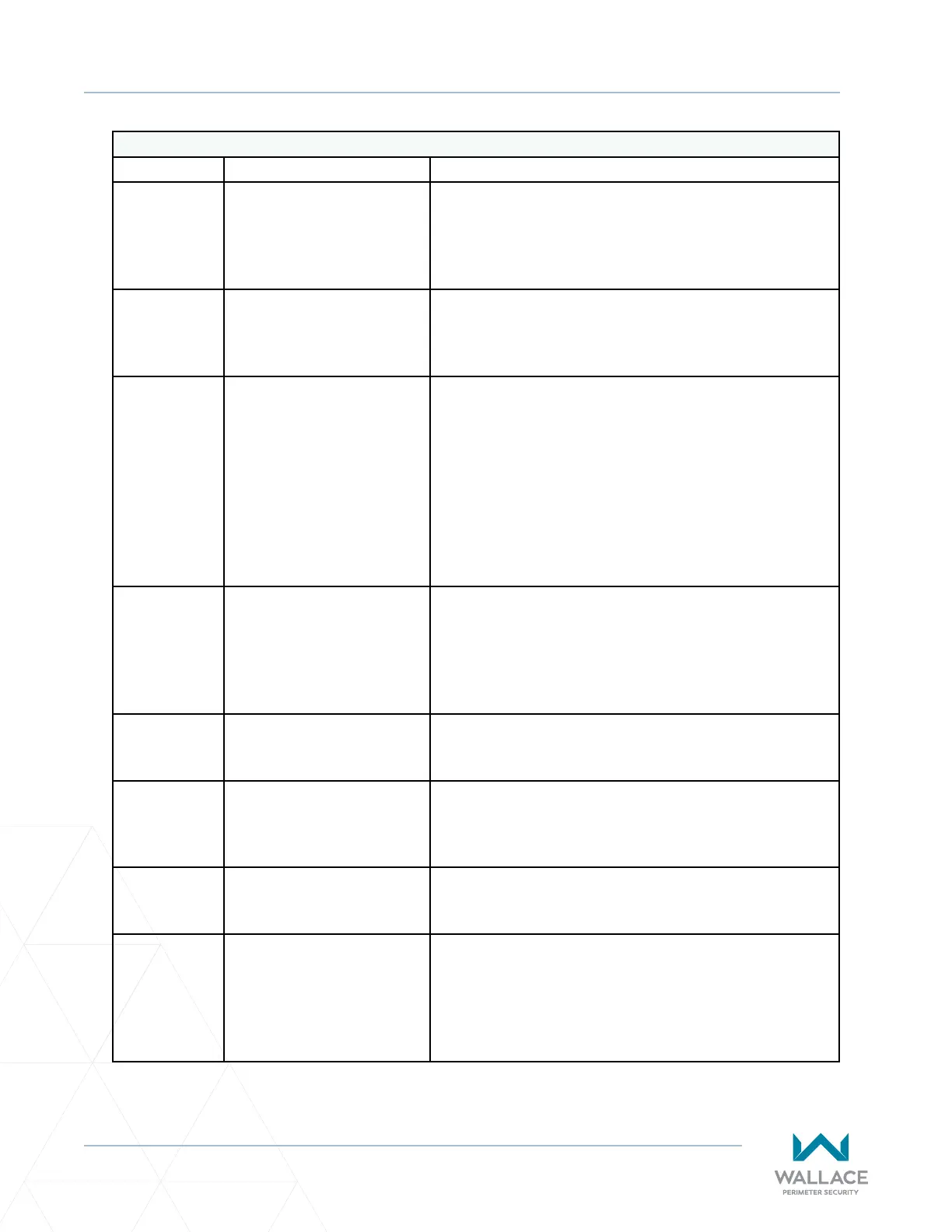
TROUBLESHOOTING
General Hardware Faults
Error Descripon Cause
F.510
Motor / intermediate
circuit over-current Limit 2.
‒ Wrong motor data set (P.100 – P.103).
‒ Non-adjusted voltage increase / boost set (P.140
or P.145).
‒ Gate scks.
F.515
Motor protecon funcon
detected over-current.
‒ Incorrect motor curve (motor rated current) set
(P.101).
‒ Too much boost (P.140 or P.145).
F.519
IGBT driver chip detected
over-current.
‒ Short circuit or ground fault on motor terminals.
‒ Motor rated current seng signicantly
inaccurate (P�100 doesn’t match nameplate rang
for the motor).
‒ Too much boost applied (P140 or P145 sengs
too high).
‒ Motor winding defecve.
‒ Momentary interrupon of the External Stop
circuit.
F.520
Over-voltage in
intermediate circuit Limit 2.
‒ Brake chopper interference / defecve / missing.
‒ Feed voltage much too high.
‒ Motor feeds back too much energy in generator
mode, gate moon energy cannot be suciently
brought down.
F.521
Over-voltage in
intermediate circuit.
‒ Input voltage supply too low, usually at load.
‒ Load too great / nal stage or brake chopper fault.
F.524
External 24 V supply missing
or too low.
‒ Overload but no short circuit.
‒ When 24V is shorted the controller voltage does
not ramp up and indicator light V306 comes on.
F.525
Over-voltage at the line
supply input.
‒ The line supply for the Controller is too high.
‒ Line supply is uctuang.
F.530
Temperature cooler outside
of working range Limit 1.
‒ Excessive load on nal stages or brake chopper.
‒ Ambient temperature too low for controller
operaon.
‒ Clock frequency of nal stage too high (Parameter
P�160).