92
wallaceperimetersecurity.comPhone: 866.300.1110
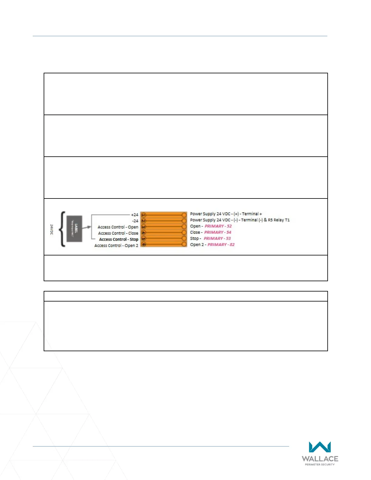
ELECTRICAL CIRCUIT – OPERATOR
Electrical Circuit – OPERATOR
1. ANY OPEN DEVICE
Any device used to open the gate, such as a pushbuon, key switch or access system typically connects
to terminal #3 and #6 in the primary operator.
2. ANY CLOSE DEVICE
Any device used to close the gate, such as a pushbuon, key switch or access system typically connects
to terminal #4 in the primary operator.
3. ANY STOP DEVICE
Any device used to stop the gate during movement, such as a pushbuon key switch or access system
typically connects to terminal #5 in the primary operator.
Always refer to site-specic drawings issued for the project you are working on for actual electrical
connecons and installaon methods.
4. EXTERNAL STOP DEVICE
External stop device is dened as any N.C. maintained pull-to-release, maintained twist-to-release and/
or maintained twist-key-to-release device used for an external stop, which when acvated, shuts down
all gate funcons. There is 1 (N.C.) external stop input, external stop 1 terminals #41 to #42. Terminals
#31 and #32 are provided for an addional external stop input, if needed. To install an external device
the corresponding jumper needs to be removed. Typical example: