SPEEDGATE Installation and Maintenance Manual Revision 1 - MAY 2023
45
SPEEDGATE INSTALLATION
SpeedGate Installaon
The SpeedGate installaon should only be carried out by personnel qualied by Wallace Perimeter Security.
REQUIRED FACILITIES:
The following facilies must be present at the installaon site:
• Electricity for the operator cabinet (208 – 240V single phase, 2 hot wires, 1 ground wire).
• 20 AMP dedicated circuit breaker (recommended).
• Control wiring to the central controls (depending on the chosen control system).
INSTALLATION CONSIDERATIONS:
When carrying out all hoisng acvies, make sure that the strength of the hoisng
straps is sucient to bear the weight to be hoisted. Pay aenon to the angle of the
hoisng straps. The greater the angle, the lower the drawing strength of the hoisng
straps. (Consult the strap manufacturer for more informaon).
During installaon, avoid damage to the coang layer of the SpeedGate if it is powder-coated.
The following step-by-step instrucons for the installaon and connecon of the SpeedGate should be
followed.
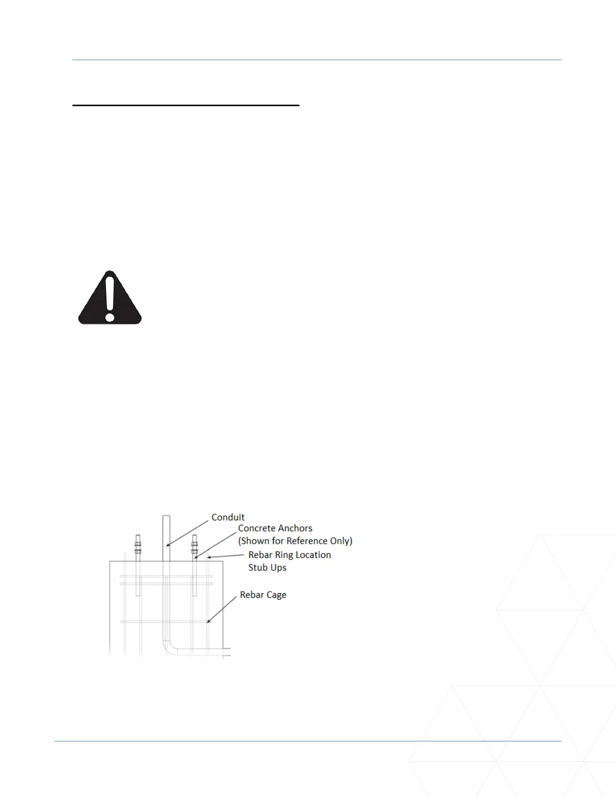
Foong and Foundaon Installaon
1. See standard product drawings for recommendaons on foundaon design. Final design by others.
Figure 7. Typical Foong/Foundaon