46
wallaceperimetersecurity.comPhone: 866.300.1110
SPEEDGATE INSTALLATION
2. Using a leveling device, check to see that the foundaons for the SpeedGate are level with each other.
In case of foundaons that have been set to dierent elevaons, the anchor bolts will need to be
lengthened to accommodate the inconsistency. SpeedGate columns should always be placed as
close as possible to the concrete foundaon, using leveling nuts in all cases.
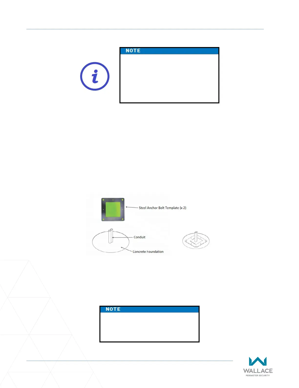
3. Place each steel anchor bolt template on the prepared foundaons (see Figure 8) making sure that
templates are aligned and centered on the foundaons. If the SpeedGate is being installed near a
wall, object or pre-exisng opening make sure that each side of the template is the same distance
from the wall, object or pre-exisng opening. See SpeedGate site-specic general layout drawings
that are provided by Wallace Perimeter Security for exact dimensions of the gate foundaons.
Figure 8. Anchor Bolt Template and Foundaon
The foong details are a guideline
and are only for reference, as local
environmental and soil condions
should be taken into account. Contact
Wallace Perimeter Security for more
informaon.
4. Ensure that the required conduits t in the center of the anchor bolt template (see Figure 8). Using
1” grade 8 anchor bolts (or equivalent), imbed the anchors using epoxy chemical anchor (HILTI HVU2
1” X 8 1/4” or equivalent).
The manufacturer’s wrien
instrucons must be read and followed
prior to using the epoxy system.