SPEEDGATE Installation and Maintenance Manual Revision 1 - MAY 2023
55
INSTALLATION ADJUSTMENTS
Installaon Adjustments
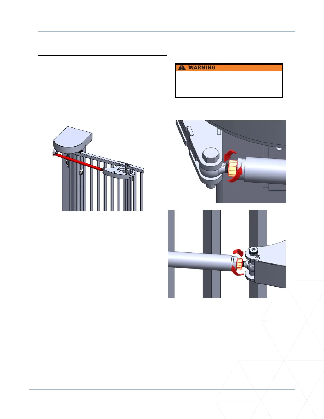
Drawbar Adjustment Procedure
Deacvate gate during drawbar
adjustment.
The SpeedGate gate uses a length-adjustable drawbar to align and center the panels.
1. To complete the drawbar adjustment, rst
ensure the gate is in the fully closed posion.
To move the gate closed manually, use the
manual brake disconnect located under the
motor in each column. Pull down on the
cable unl you see the cable clamp and lock
the clamp into the groove provided along the
top edge of the lower access door opening.
Refer to “Manual Operaon Using the Brake
Disconnect Cable” on page 112.
Close the gate, then release the manual brake
disconnect by pulling down on the cable and
removing it from the groove so that it hangs
free. Releasing the manual brake disconnect
ensures the gate will not move and drawbar
will not dri as you complete the adjustment.
2. You will need a 1-1/8 inch wrench to loosen
o the nuts on either side of the drawbar.
A 1-1/4 inch wrench is required to hold the
drawbar in place while loosening o each nut.
The threading on each side is opposite.
3. Once the nuts have been loosened, a 1-1/4
inch wrench may be used to rotate the
drawbar either clockwise or counterclockwise.
The direcon of rotaon will either shorten or
lengthen the drawbar, moving the gate panels
toward you or away from you.