56
wallaceperimetersecurity.comPhone: 866.300.1110
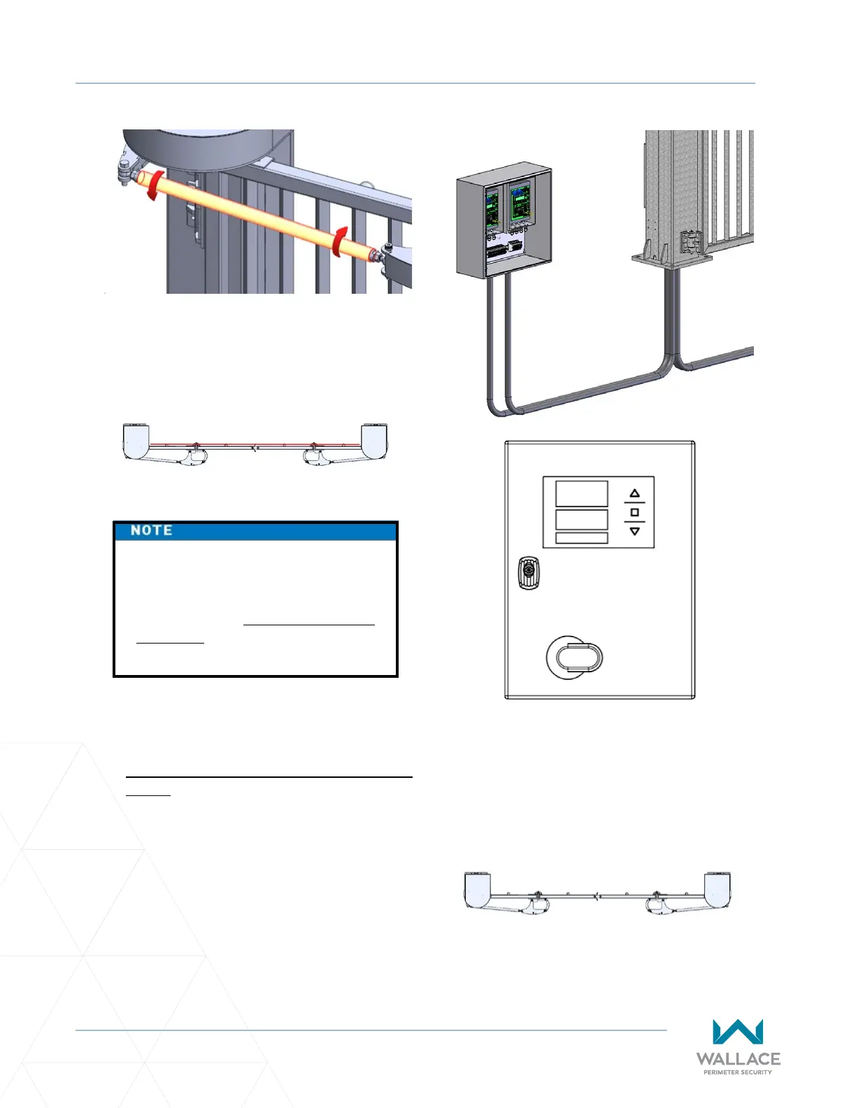
INSTALLATION ADJUSTMENTS
4. Once adjusted so that the gate panels are
square at a 90-degree angle to the roadway,
ghten the nuts on either end of the drawbar
to lock in the current posion.
5. Set the gate limits. Refer to “Installaon and
Commissioning Checklist: Seng Gate Limits”
on page 10.
6� Ensure trac, both pedestrian and vehicle,
is clear and then test the gate. Turn operator
power ON and press the operator foil keypad
up arrow to test the gate open cycle.
Test the gate close cycle by pressing the
operator foil keypad down arrow.
7. Ensure the open limit is suitable and the gate,
when closed, does not bind on the steel vercal
catches. If there is binding, further adjust the
drawbar or electronic limit as needed.
The gate should be installed, all
wires terminated properly, and all
mechanical adjustments, (including
drawbar) made prior to seng the
gate limits via the foil keypad on the
controller in the Operator Cabinet.