10
wallaceperimetersecurity.comPhone: 866.300.1110
INSTALLATION AND COMMISSIONING CHECKLIST
Installaon and Commissioning Checklist
Complete Step Descripon Manual
Secon
Reference(s)
5.2 Operator Power-up:
5.2.1 Using the manual brake disconnect, move the gate’s panels to
the halfway point between the open and closed posion. Clear
the gate travel area of all obstrucons and apply power to the
gate controller.
page 112
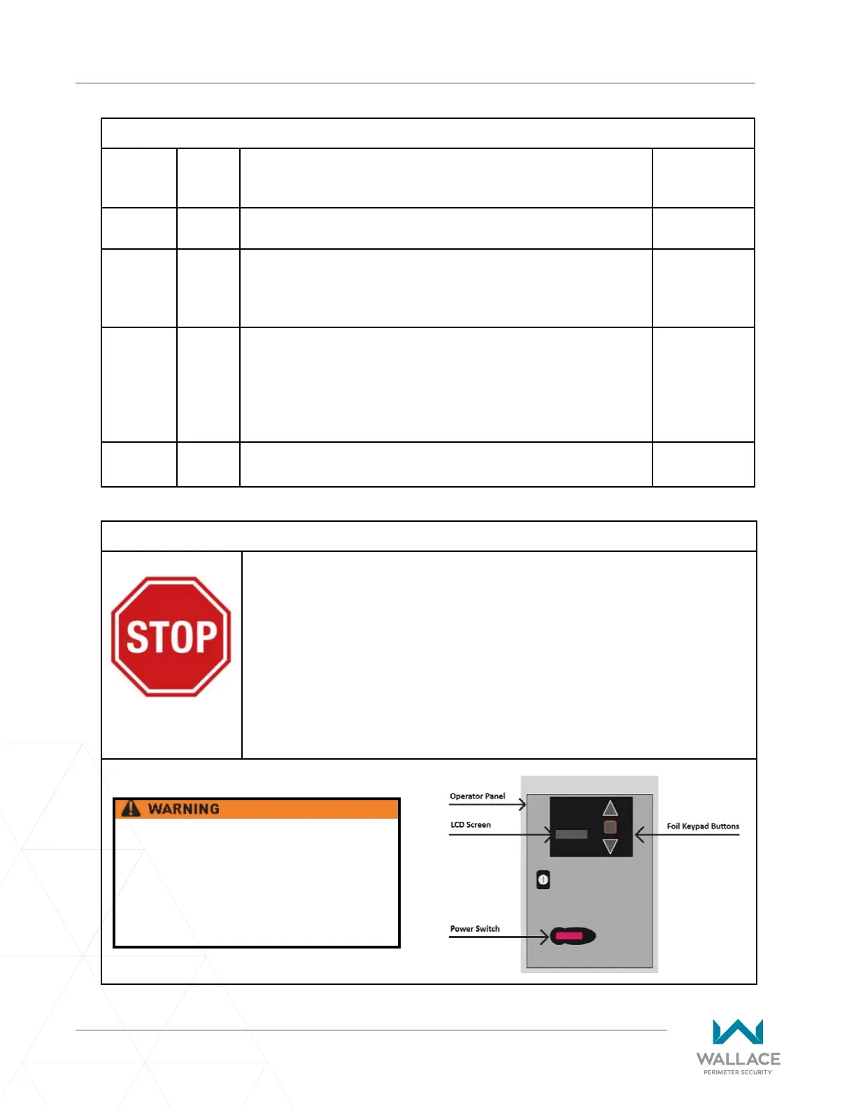
5.2.2 The LCD board on the top le-hand corner of the controller
will display a “boot-up.” Using the foil keypad buons on each
operator cabinet press the UP arrow and observe the gate panels.
If the corresponding gate panel opens, the VFD motor wiring is
correct. If the gate panels are not moving in the desired direcon,
follow step 5.3.3-J, under Seng Gate Limits, to resolve this.
--
5.3 Set Gate Limits, in accordance with the following instrucons, in
the order that they are given.
See below.
Installaon and Commissioning Checklist: Seng Gate Limits
A� DO NOT SET GATE LIMITS UNTIL THE GATE IS INSTALLED, ALL WIRES ARE
TERMINATED PROPERLY, AND ALL MECHANICAL ADJUSTMENTS (INCLUDING
DRAWBAR) ARE COMPLETE.
B� ALL ENTRAPMENT SAFETY DEVICES MUST BE INSTALLED PRIOR TO SETTING
THE GATE LIMITS.
C� Set Gate Limits, in accordance with the following instrucons, in the order
that they are given.
Do not change any other parameters
than the ones listed in the instrucons
below. Doing so might cause the gate to
not funcon properly possibly causing
damage, injury and/or death.