38
wallaceperimetersecurity.comPhone: 866.300.1110
INSTALLER AND USER SAFETY CONSIDERATIONS
ENTRAPMENT AND PINCH POINTS
Safety measures have been taken in the design of the SpeedGate in order to reduce these risks as much
as possible. These risks can be limited even further by taking risks into account when posioning the
gate and by observing the safety instrucons.
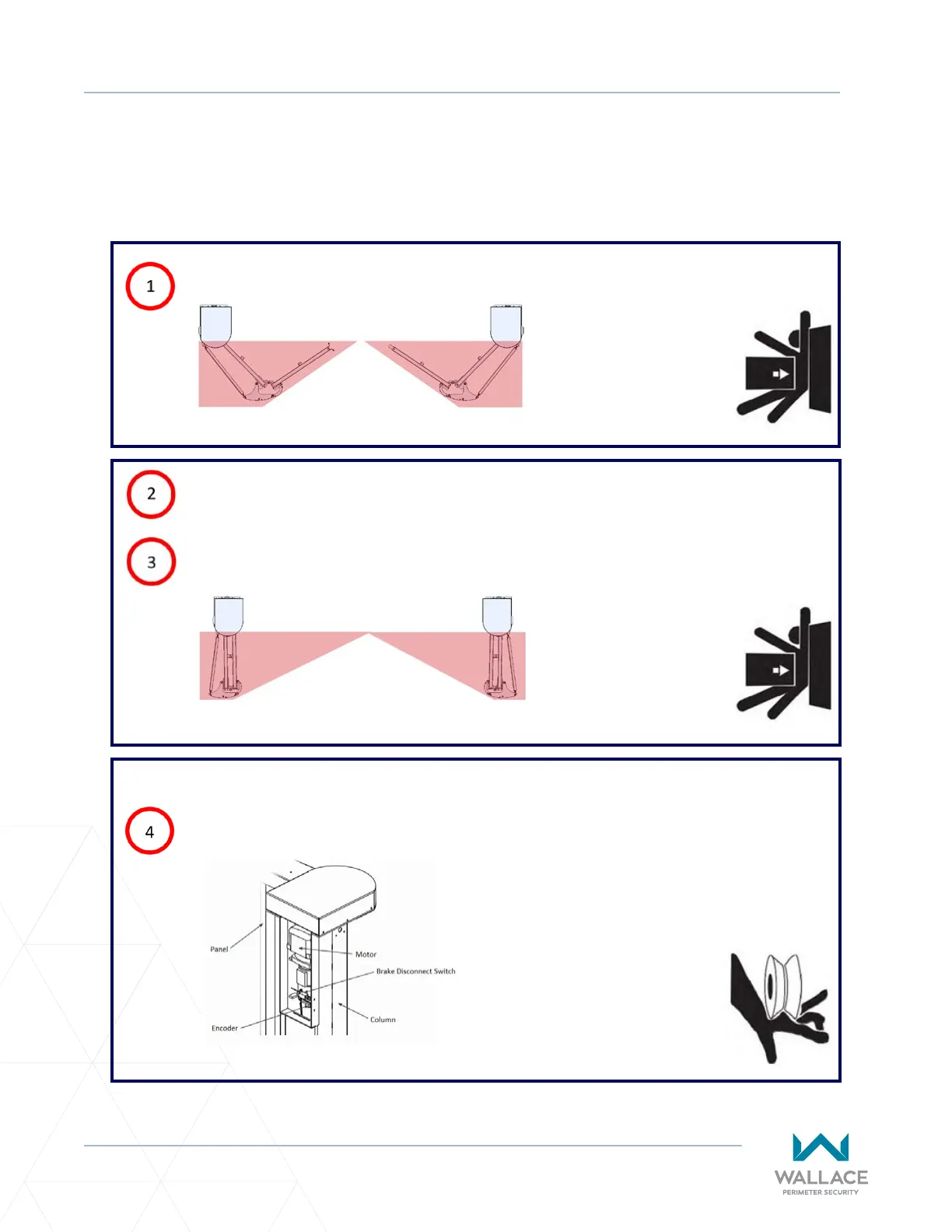
Between the outermost panel secons.
Figure 5.1. Panels Half-Open: Top View
Between the innermost and outermost panel secons.
Figure 5.2. Panels Open: Top View
Between the innermost panel secon and a parallel wall or object.
IN THE GATE STRUCTURE
Inside the Column: Between the moving parts in the drive box.
Figure 5.3. Inside the Column