74
wallaceperimetersecurity.comPhone: 866.300.1110
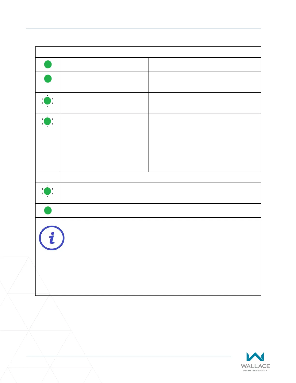
PHOTO EYE ALIGNMENT
Table 9. Vericaon of Photo Eye Alignment
Green transmier LED ON. Power present and transmier is funconal.
Green receiver LED ON. Successful system alignment, power present and
receiver is funconal.
Green receiver LED FLASHING. Obstrucon between photo eyes is present. (On
the receiver side, single-pole relay clicks.)
Green receiver LED FLASHING when
there is NO OBSTRUCTION present.
FAULT: Beam blocked or not aligned. The receiver
is not “seeing” the transmier.
Recommended acon(s):
1. Clean the sensor (beam output and receiver)
with a so, clean, dry cloth.
2. Re-align transmier and receiver.
3. Check voltage and current with mulmeter.
TEST:
1) Place an obstrucon (e.g., hand) in front of the receiver. Green receiver LED should be
ON and ashing, indicang obstrucon detecon.
2) Remove obstrucon from the receiver. Green receiver LED should be ON and not
ashing.
Opcal crosstalk occurs when a photoelectric receiver responds to light from an adjacent
emier. Crosstalk is occurring if the transmier is solid green and the receiver appears
dead (LED not lit), except when an obstrucon is detected, in which case the green
receiver LED commences ashing.
If re-alignment or reposioning of transmier and receiver does not resolve crosstalk
and/or the interference is occurring at a site with more than one SpeedGate, decrease
the sensivity seng on the receiver to the posion where the green LED on the receiver
starts to ash. Then increase sensivity seng one quarter turn.