82
wallaceperimetersecurity.comPhone: 866.300.1110
INSTALLATION INSTRUCTIONS FOR OPTIONAL VEHICLE DETECTORS
Installaon of Vehicle Detecon Ground-Loop Systems
3.1.3 It is highly recommended that a connuous length of wire be used to form the loop and feeder
to the detector. Loop wire is typically 14, 16, 18, or 20 AWG with cross-linked polyethylene
insulaon which is very resistant to moisture absorpon and provides good abrasion resistance.
3.1.4 The wire used in the loop should have an insulaon rated for direct burial. Since moisture
can cause signicant changes in the dielectric constant of the wire insulaon, which results
in excessive loop (frequency) dri, choose a wire with an insulaon which is impervious to
moisture. Wires with Polyvinyl Chloride (PVC) insulaon (i.e., those labeled TFFN, THHN, and
THHN-THWN) should NOT be used since they tend to absorb moisture and crack easily.
3.1.5 Avoid potenal damage to the loop wire by inserng the wire in the boom of the saw slot
using a wooden sck or other blunt instrument. Ensure wires are pressed rmly into the slot.
Loose wires can cause false calls due to vibraon or sudden movement.
3.1.6 In most cases, the saw cut will end at the edge of the pavement or at a stub-out for a conduit.
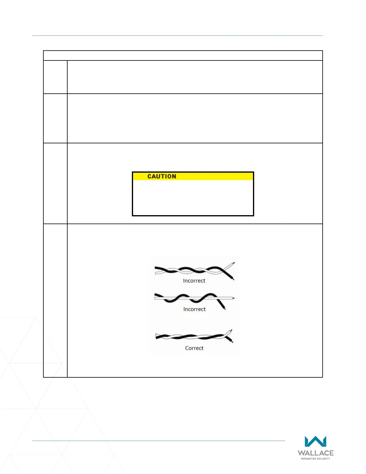
Where the wires leave the saw cut they must be twisted together with a minimum of six (6)
twists per foot (30.5cm). See Figure 19.
Figure 19. Correct Loop Wire Twist Conguraon
NEVER use a screwdriver or a sharp
object for loop inseron, as this can
puncture loop wire.