84
wallaceperimetersecurity.comPhone: 866.300.1110
INSTALLATION INSTRUCTIONS FOR OPTIONAL VEHICLE DETECTORS
Installaon of Vehicle Detecon Ground-Loop Systems
8. If an automac exit loop is required, a third detector relay will be required. If an automac
exit loop is required, a third detector relay will be required (not supplied by Wallace Perimeter
Security). This auxiliary detector should be powered from terminals #1 and #2 and wired as a
N.O. contact to terminals #1 and #3.
9. Choose a sealant carefully to match the applicaon and the pavement type. Hard seng
epoxies should not be used with asphalt. Cauon should be observed when using hot sealants,
as high temperatures can damage or destroy wire insulaon. Please refer to the jurisdicon/
state’s department of transportaon specs for trac light loop sealant.
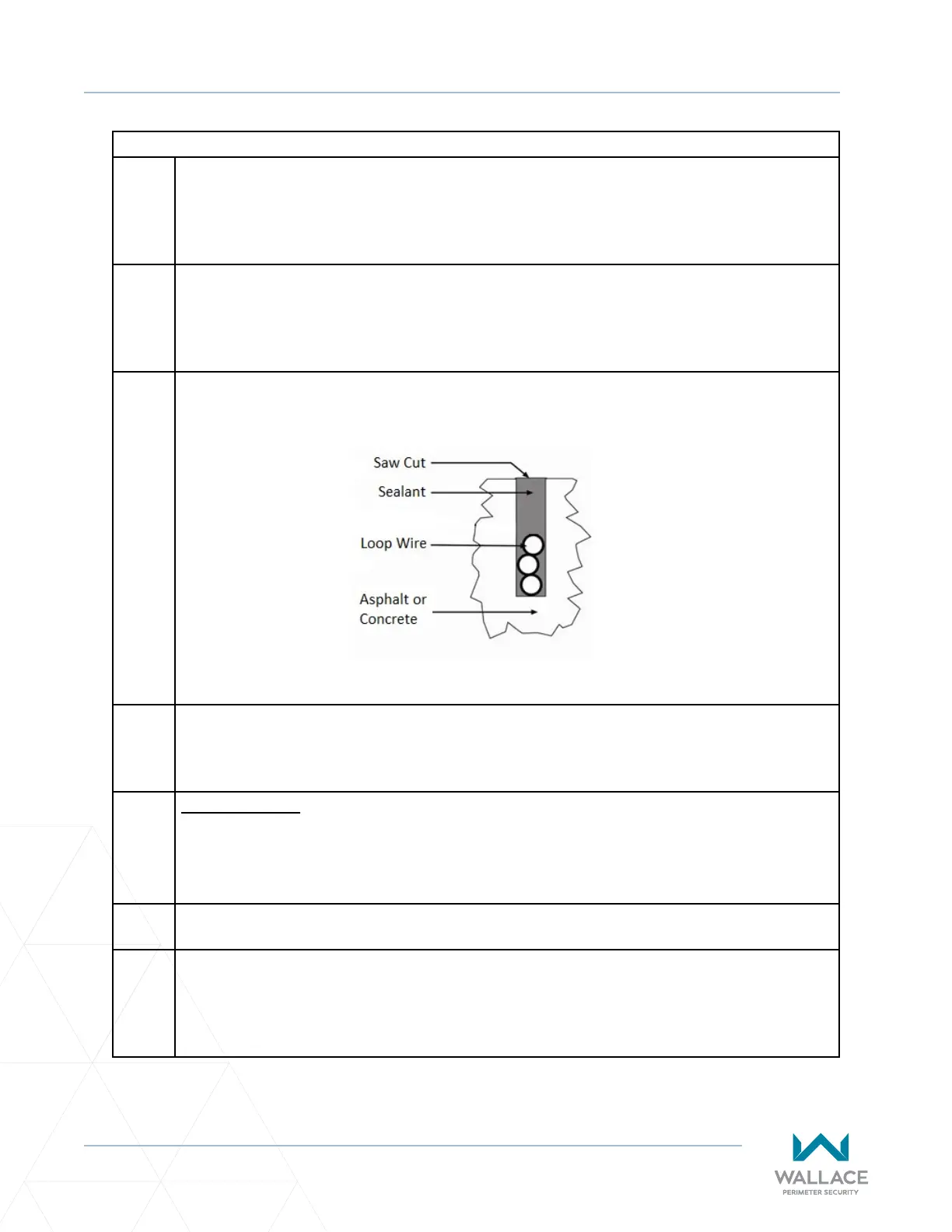
9.1 When properly applied, the sealant should completely cover the loop wire(s). Since the sealant
forms a barrier between the wire and the environment, it is essenal that the wire(s) are
completely covered. See Figure 20 for the proper end result.
9.2 There MUST be no voids which might allow water to collect within the slot. The water will
freeze and expand during freezing condions. Freeze/thaw cycling will eventually push the
loop wires up and out of the slot, resulng in a loop failure.
10.
Loop Diagnoscs
The following tests cannot guarantee a funconing loop, but failure of either test means that
the loops are denitely suspect, even if sll funconal at the me of tesng.
10.1 TEST 1 - Resistance of the loop and loop lead wires should not exceed 4.0 ohms.
10.2 TEST 2 - The resistance to earth, as measured with a 500V “Megger”, should be 100 Megohms
or more. Loops may funcon at less than 100 Megohms but will not be reliable (e.g., when the
ground is wet from rainfall). Low resistance indicates broken or moisture-saturated insulaon.
This is common if inappropriate wire insulaon has been used.
Figure 20. Proper Sealant Applicaon