Do you have a question about the Waters ACQUITY and is the answer not in the manual?
Contains legal notices regarding document reproduction and rights, and terms of use.
Lists registered and unregistered trademarks of Waters Corporation and third parties.
Provides contact information for submitting feedback and suggestions for document improvement.
Details how to reach Waters for product-related inquiries via various channels.
Explains the meaning of hazard symbols and their importance in documentation.
Details specific safety warnings related to the device, such as power cord and leaks.
Warns against placing liquid-filled containers on or near equipment to prevent damage.
Advises on proper placement of the instrument for easy power cord disconnection.
Lists symbols found on the device, system, or packaging with their definitions.
Describes the intended audience and scope of the manual.
Specifies the detector's application in LC/MS and its limitations.
Outlines methods and requirements for calibrating LC systems using standards.
Describes procedures for running QC samples to ensure instrument performance.
States compliance with FCC rules and conditions for operation.
Declares compliance with Canadian ICES-001 standards.
Assigns classification based on CISPR 11 standards for ISM instruments.
Provides guidance on avoiding electromagnetic interference for proper operation.
Explains different data acquisition modes like Scanning, SIR, and RADAR.
Describes the path of ions through the instrument from LC to detection.
Details the instrument's automatic start-up checks for calibration and quadrupole settings.
Explains how to introduce samples into the detector from LC or syringe pump.
Describes the internal and external pumps that create the instrument's vacuum.
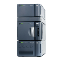
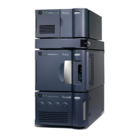
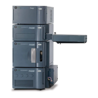
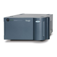
Provides details to help identify the specific QDa model being used.
Introduces the optional accessory for diverting eluent and supporting loop injections.
Guides on making electrical and vacuum connections to the detector's rear panel.
Details requirements for a grounded power source and connection steps.
Provides instructions for connecting the probe assembly to the source enclosure.
Outlines the sequence for powering on and initiating instrument operation.
Explains the automatic function that stops LC flow during standby or gas failure.
Lists periodic tasks to ensure optimum instrument performance.
Recommends using Waters Quality Parts for system integrity and how to order them.
Provides safety warnings and procedures for replacing instrument fuses.
Describes the system for proactive service and support via remote access.
Details the steps to manually submit a support request.
Reminds users of safety considerations during maintenance procedures.
Guides on removing and reattaching the source enclosure for component access.
Covers cleaning and replacing parts like the sample cone and ion block.
Provides instructions for cleaning the exterior of the mass spectrometer.
Details procedures for cleaning ion guide components to maintain signal.
Instructs on daily inspection and emptying of the exhaust trap bottle.
Describes how to empty the trap bottle for the backing pump.
Explains when and how to check and replace backing pump oil.
Provides notes on the correct use of gas ballasting to prevent pump damage.
Refers to troubleshooting section for this replacement task.
Details procedures for replacing the valve on specific instrument models.
Explains symbols indicating risks like death, injury, or adverse reactions.
Alerts users to potential damage or sample integrity issues from misuse.
Warns about equipment damage from solvent spills and proper bottle placement.
Highlights the need for eye protection and chemical-resistant gloves.
General warnings about unauthorized modifications and proper usage.
Provides specific warnings related to fuse replacement safety.
Lists electrical and handling symbols with their descriptions and meanings.
Lists height, width, depth, and weight for different detector models.
Details operating temperature ranges and humidity levels.
Provides information on protection class, voltage, frequency, and power draw.
Lists details for USB, Com Port, Contact Closure Outputs, and Event Inputs.
Refers to a separate document for information on preventing contamination.
Warns about hazards of Hexane and THF and recommends ventilation.
Lists materials exposed to solvents and compatible solvents for KAD version.
Lists materials exposed to solvents and compatible solvents for KAB version.
Guides on making electrical and vacuum connections to the rear panel.
Details the process for attaching the diaphragm pump.
Outlines the installation of the rotary backing pump.
Provides instructions for connecting the nitrogen supply and regulator.
Guides on connecting/disconnecting the KAB exhaust valve assembly.
Guides on connecting/disconnecting the KAD exhaust valve assembly.
Details connecting the exhaust trap bottle and related tubing configurations.
Explains how to connect the waste container for specific QDa models.
Provides steps to connect the nitrogen exhaust trap and associated tubing.
Details connecting the workstation and setting up the system.
Guides on establishing network connections for the system.
Describes the rear panel connectors for I/O signals and their functions.
Refers to the section on connecting to the electricity source.
Highlights safety precautions, especially grounding, for the diverter valve.
Provides steps for fitting the diverter valve assembly onto the detector.
Refers to rear panel connections for the diverter valve.
Explains how to set up flow paths for divert or loop injection modes.
Details connecting waste tubing for different diverter valve configurations.
Covers manual and programmed operation of the diverter valve.
Outlines cleaning and replacement of diverter valve components.
Guides on how to safely detach the diverter valve assembly.
| Flow Rate Range | 0.001 to 2.000 mL/min |
|---|---|
| Injection Volume | 0.1 to 100 μL |
| Maximum Pressure | 15, 000 psi |
| Sample Temperature Control | 4 to 40 °C |
| Data Acquisition Rate | Up to 80 Hz |
| Detection Wavelength Range | 190 to 800 nm |
| Detector Type | PDA (Photodiode Array) |