Recommendation: To ensure that the sample flow direction is correct for each command,
plumb the connections as shown in this document.
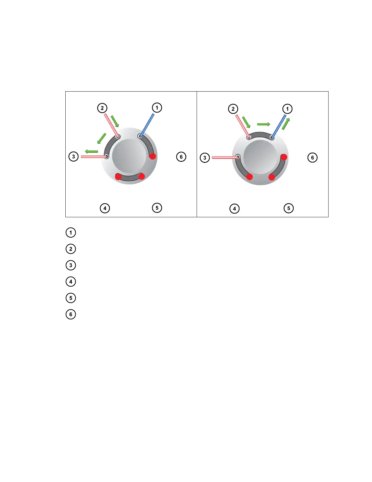
Figure E–7: Common configuration of the diverter valve operating in divert mode
Valve position 1 - ON = Flow to QDa Valve position 2 - OFF = Flow to waste
To waste (blue PEEK tubing, 0.01-inch internal diameter)
From LC (red PEEK tubing, 0.005-inch internal diameter)
To QDa (red probe assembly, 250 mm)
Not used (plugged port)
Not used (plugged port)
Not used (plugged port)
June 15, 2017, 715003956 Rev. F
Page 123