English
ACCESSORIES
7.2BACKPLANEREPLACEMENT
Thecontrolaccessoriesaremountedinthebackplaneslots.Theslotsareinterchangeable,andanyaccessory
canbemountedinanyslotinanyquantity(exceptforcommunicationnetworkaccessories,whicharelimitedtoone
perdrive).Bydefault,theCFW900issuppliedwiththebackplaneCFW900-4SLOTS,whichallowstheinstallation
ofupto4accessories(slotsAtoD).ItispossibletoreplacetheCFW900-4SLOTSwiththeCFW900-7SLOTS,
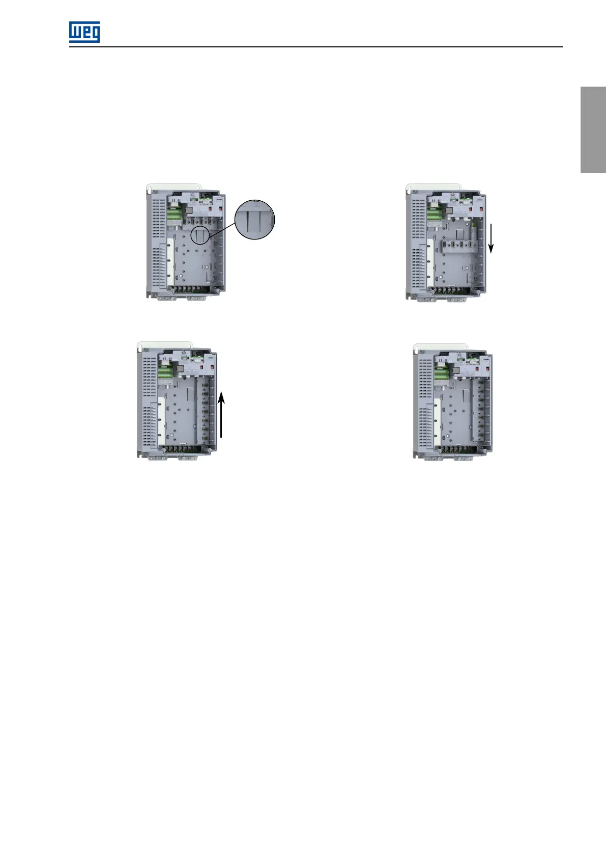
whichexpandstheconnectionupto7accessories,followingthestepsinFigure7.1.
(a)PressthelatchthatholdstheCFW900-4SLOTS(b)PulltheCFW900-4SLOTSasindicatedandremove
itfromtheproduct
(c) Positionthe CFW900-7SLOTS asshown inthe
figureandpushitintheindicateddirection
(d)Make surethat theCFW900-7SLOTS lockedin
place
Figure7.1:ReplacingtheCFW900-4SLOTSwiththeCFW900-7SLOTS
7.3INSTALLINGTHECONTROLACCESSORY
Thecontrolaccessoriesareeasyandquicklyinstalledontheinvertersusingtheplug-and-playconcept.Theymay
beorderedseparatelyandwillbeshippedinindividualpackagescontainingthecomponentsandthemanualswith
detailedinstructionsfortheproductoperationandprogramming.Whenanaccessoryisconnectedtotheinverter,
thecontrolcircuitryidentifiesthemodelandinformsthecodeoftheconnectedaccessory.Theyshouldonlybe
installedorchangedwiththeinverterturnedoff,followingthestepspresentedbelowandexemplifiedinFigure7.2.
1.RemovetheHMIfromtheinverterfront.
2.Removethetwoscrewsanddetachthefrontcover.
3.Inserttheaccessoryintooneoftheavailableslotsonthebackplane.(A)
4.Fastenthegroundingscrew.(B)
5.Maketheconnectionstotheplug-inconnectorandplugitintotheaccessory.(C)
6.Connectthecableshieldtothegroundingplateusingmetalclamps.(D)
7.Attachtheidentificationlabels(suppliedwiththebackplane)totheaccessoryandtotheplug-inconnector.
(E)
8.PutthefrontcoverandHMIbackinplace.
CFW900|93