English
HMI
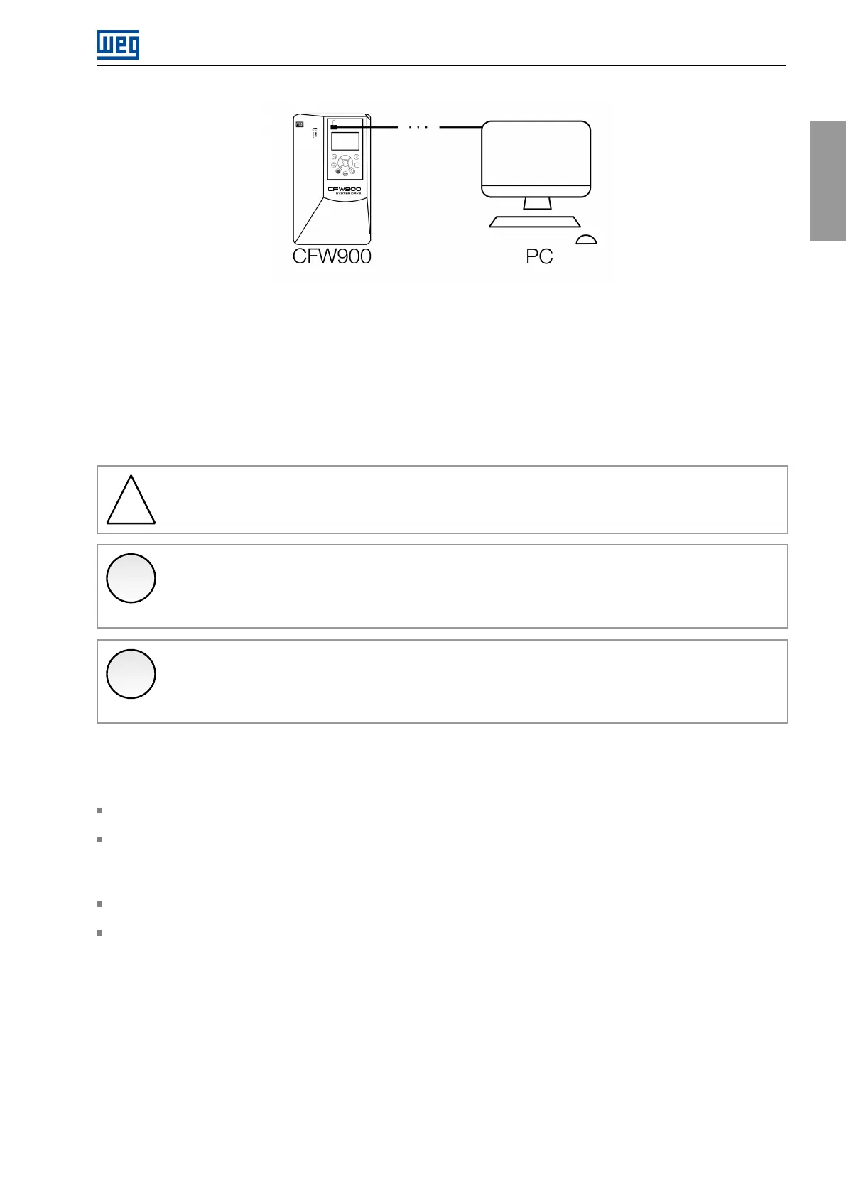
Figure4.16:CFW900USBconnectiontoacomputer
Whentheinverterisnotpoweredorconnectedtoanexternal24Vdcpowersupply,thecontrolcircuitispowered
bytheUSBport,whichimposessomerestrictions.Onlythecontrolcircuitwillbeenabled;othercircuits,control
accessoriesandnetworkswillbedisabled.
TheUSBpowersupplyallowsreadingandwritingparametersviaHMIandconnectiontotheWPS,butthe
parametersofconnectedaccessorieswillnotbeavailable,aswellasparameterslinkedtoregulationfunctions
(whichdependontheoperationofotherpartsoftheinverter). FunctionsthatusetheMicroSDcardwillnotbe
availableeither.
!
WARNING!
IntheUSBmode,theHMIcannotbeusedremotely.Itmustbedirectlyconnectedtotheinverter.
✓
NOTE!
OncepoweredbytheUSBport,whenmakingchangestotheinverterparametersviaHMI,waitfor
theconfirmationscreentoensurethesavingoftheparameter.
✓
NOTE!
IftheinvertercontrolcircuitispoweredbytheUSB,andanotherpowersupplyisconnected,thedrive
willreset.
4.7INSTALLINGTHEHMI
TheHMIcanbeinstalledorremovedwiththeinverterpoweredupornot.
TheHMIsuppliedwiththeproductcanalsobeusedforremotecommandoftheinverter. Inthiscase,usea
cablewithD-Sub9(DB-9)maleandfemaleconnectorswithpin-to-pinconnections.Itisrecommendedtouse
theM3x5.8spacerssuppliedwiththeproduct.Recommendedtorque:0.5N.m(4.50Ibf.in).
TheHMIcablescanbesuppliedasaccessories,andthelistofavailableitemsisinTable7.1.
ThemaximumlengthoftheHMIcablesisspecifiedinFigure8.10.
CFW900|55