English
INSTALLATIONANDCONNECTION
!
WARNING!
Forprotectionagainstelectricshock,theCFW900-REL-01providesreinforcedisolationbetweenthe
relayoutputcontactsandothercontrolcircuits. Isolationbetweenoutputsisbasicinaccordance
withIEC61800-5-1andUL61800-5-1withvoltagelimitsof60Vdc/25Vac.Inordertocomplywith
IECandULstandards,user-accessiblecircuitsandcircuitswithvoltageabove60Vdc/25Vacmust
notbeactivatedinthesameCFW900-REL-01.
Forthecorrectinstallationofthecontrolwiring:
UsecablegaugeaccordingtoTable3.15.
Useshieldedcablesforcontrolinputs/outputsandcommunicationnetworks.Whenthecableislongerthan30
m,groundtheshieldatbothends.
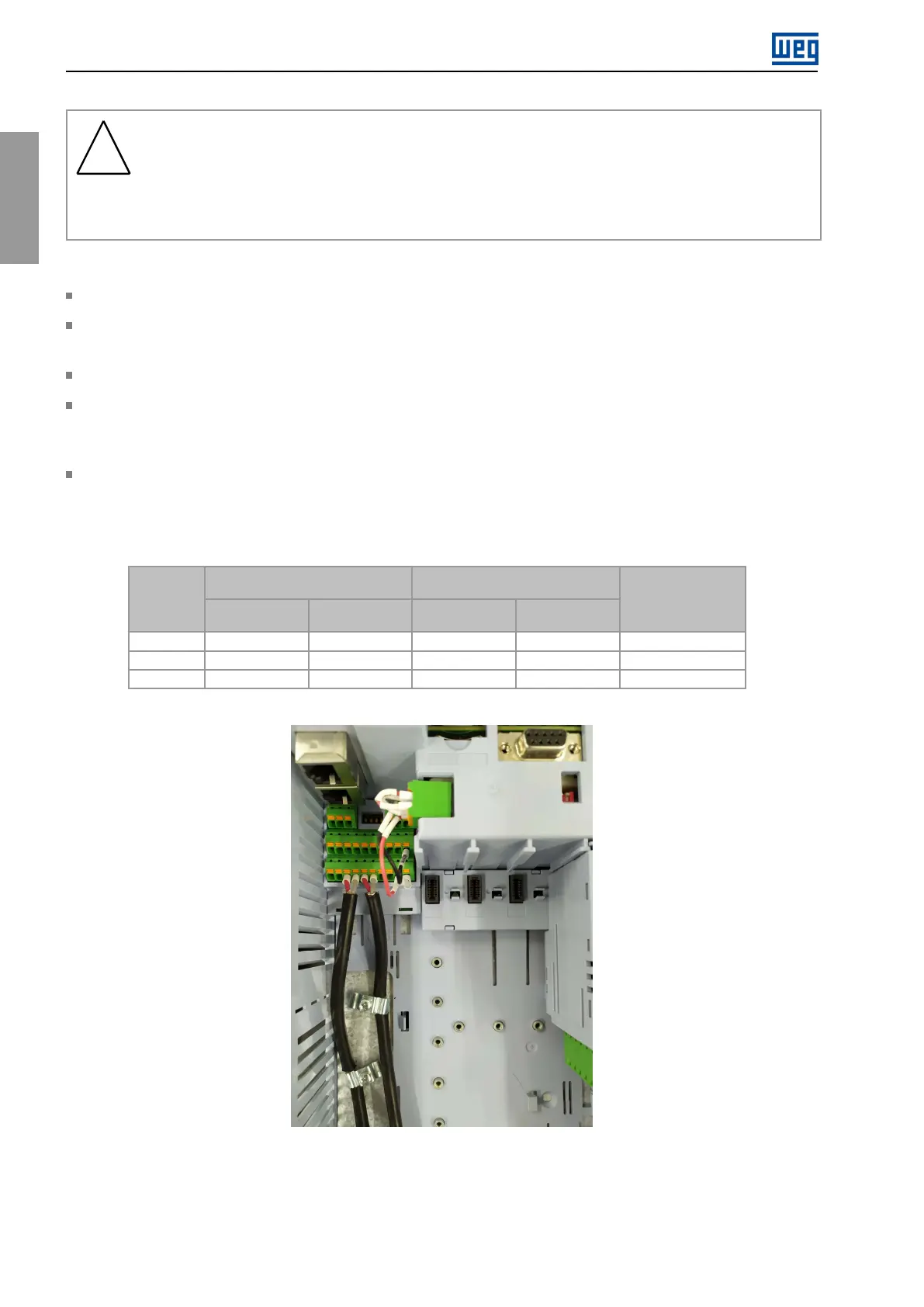
Correctlygroundtheshieldofthecables,usingtheshieldconnectionin360°,asshowninFigure3.23.
Keepthecontrol,communicationandremoteHMIcablesseparatefromtheothercables(inputandmotorcables,
110/220Vaccontroletc.)accordingtoTable3.9.Ifthethosecableshavetocrosstheothercables,itmustbe
doneperpendicularly,keepingtheminimumseparationdistanceof5cmatthecrossingpoint.
Relays,contactors,solenoidsorelectromechanicalbrakingcoilsinstalledclosetotheinvertersmaygenerate
interferenceinthecontrolcircuit.Toeliminatethiseffect,RCsuppressorsmustbeconnectedinparalleltothe
coilsofthosedevicesincaseofACpowersupply,andfreewheelingdiodesincaseofDCpowersupply.
Table3.15:Cablegaugesforcontrolconnection
Conductorgaugewithout
terminal
Conductorgaugewithwire
ferruleandinsulation
Conector
Minimum
mm²(AWG)
Maximum
mm²(AWG)
Minimum
mm²(AWG)
Maximum
mm²(AWG)
Strippingor
terminallength
(mm)
XC1
0.2(24)1.5(16)0.25(23)1.5(16)10mm
XC2
0.2(24)1.5(16)0.12(26)0.75(18)10mm
XC30
0.2(24)2.5(12)0.25(23)2.5(12)8mm
Figure3.23:Connectionexampleofcontrolcableshield
3.2.6.1Internal24VdcPowerSupplyCurrentCapacity
TheinvertersoftheCFW900linehaveaninternal24Vdc/0.8Apowersupplyusedtopowertheaccessories
connectedtoslotsAtoG.Thecurrentcapacitynotusedbytheaccessoriescanbeusedtopowerexternal
42|CFW900