English
INSTALLATIONANDCONNECTION
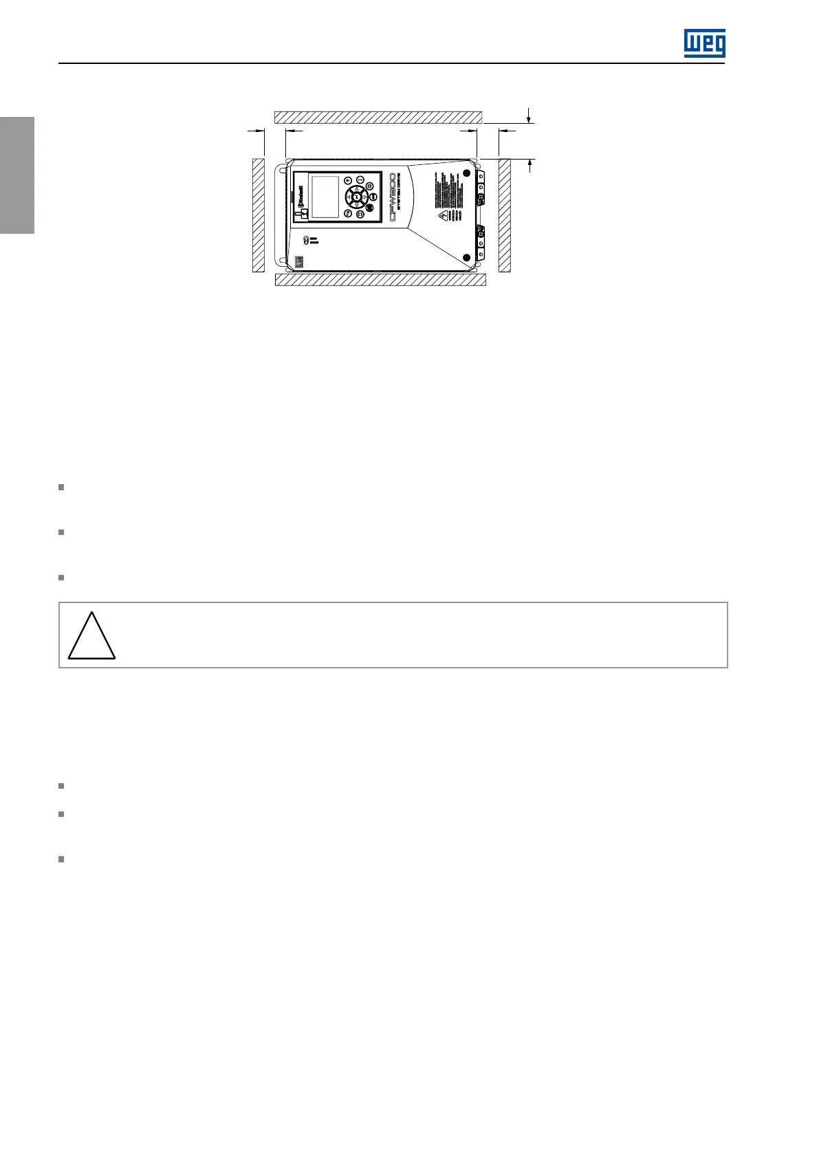
Figure3.3:
Horizontalmounting(See
Table3.3)
3.1.4CabinetMounting
Itispossibletomounttheinverters:onasurfaceoraflange.Tothatend,thefollowingconsiderationsmustbe
takenintoaccount:
3.1.4.1SurfaceMounting
Provideadequateexhaustionsothattheinternalcabinettemperatureiskeptwithintheallowableoperatingrange
oftheinverter.
Thepowerdissipatedbytheinverteratitsratedconditionandtheheatsinkfanflowattheoperationpointare
specifiedin
Chapter8.
Thepositionanddiameterofthemountingholes,accordingtoFigure3.1.
!
WARNING!
ULtype1inverterssupportsurfacemountingonly.
3.1.4.2FlangeMounting
Intheflange-mountingtype,thebackoftheinverter(whichcontainstheheatsinkandfan)isinstalledoutsidethe
panel.Therefore,thepowermodulecoolingairiskeptoutsidethecabinet.
ThemountingbracketsmustberemovedandrepositionedasshowninFigure3.4.
Dimensionsoftheopeningformountingthebackoftheproduct,positionanddiameterofthemountingholes,
asshownin
Figure3.1.
TheportionoftheinverterthatislocatedoutsidethecabinetisratedIP55/ULtype12.Toensurethatthecabinet
degreeofprotectionismaintained,adequatesealingmustbeprovidedbetweenthepanelopeningandthedrive
flange.Example:siliconegasket.
14|CFW900