English
INSTALLATIONANDCONNECTION
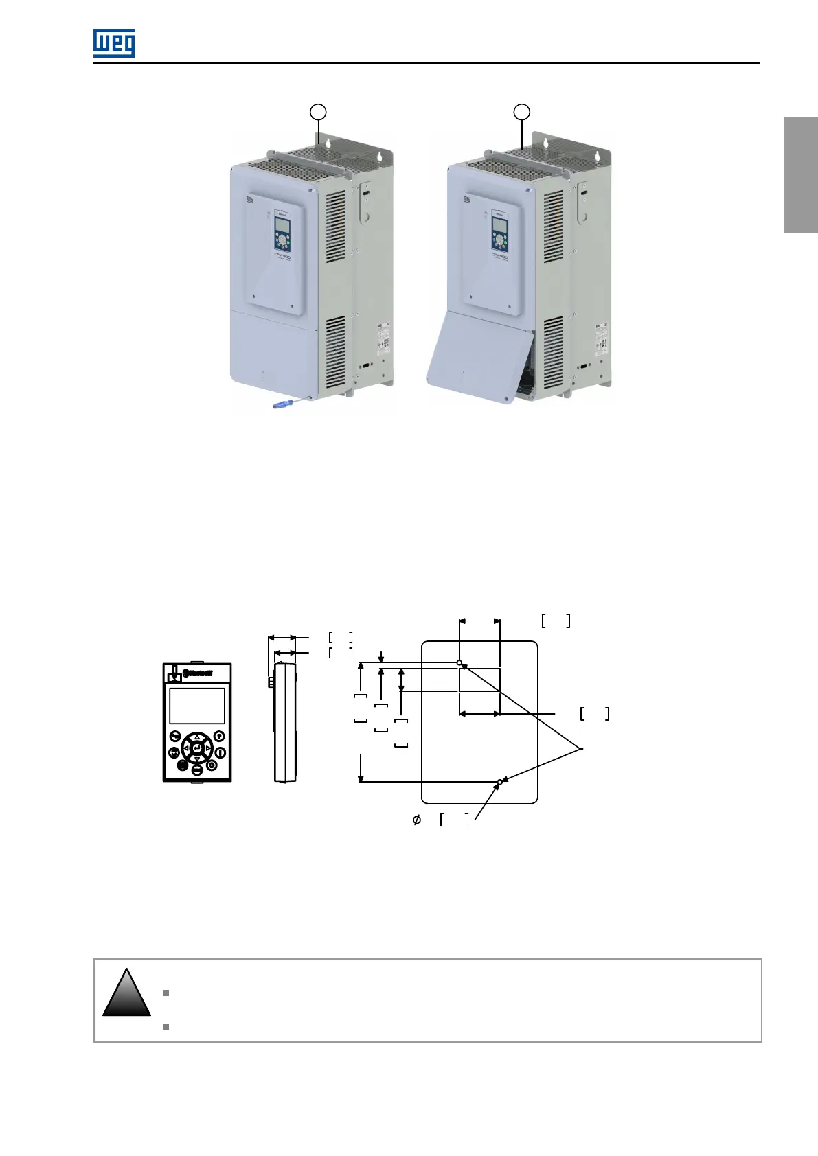
Figure3.7:Bottomfrontcoverremoval
3.1.6HMIInstallationattheCabinetDoororCommandPanel(RemoteHMI)
ThedimensionsnecessarytoassembletheHMIonthepaneldoororcontroltableareshownin
Figure3.8.Ifyou
prefer,theframeaccessorycanalsobeusedtofixtheHMIintheseplaces.
1.38
4.0
5.0
1.3835.0
0.7920.0
4.06103.0
0.20
0.16
35.0
Self-tapping screw for plastic:
Ø3mm / 7mm of maximum length
65.0 [2.56]
25.9 1.02
20.0 0.79
113.0 [4.45]
Figure3.8:DatafortheHMIinstallationatthecabinetdoororcommandpanel-mm[in]
3.2ELECTRICALINSTALLATION
!
DANGER!
Thefollowinginformationismerelyaguideforproperinstallation.Complywithapplicableregulations
forelectricalinstallations.
MakesuretheACpowersupplyisdisconnectedbeforestartingtheinstallation.
CFW900|17