English
INSTALLATIONANDCONNECTION
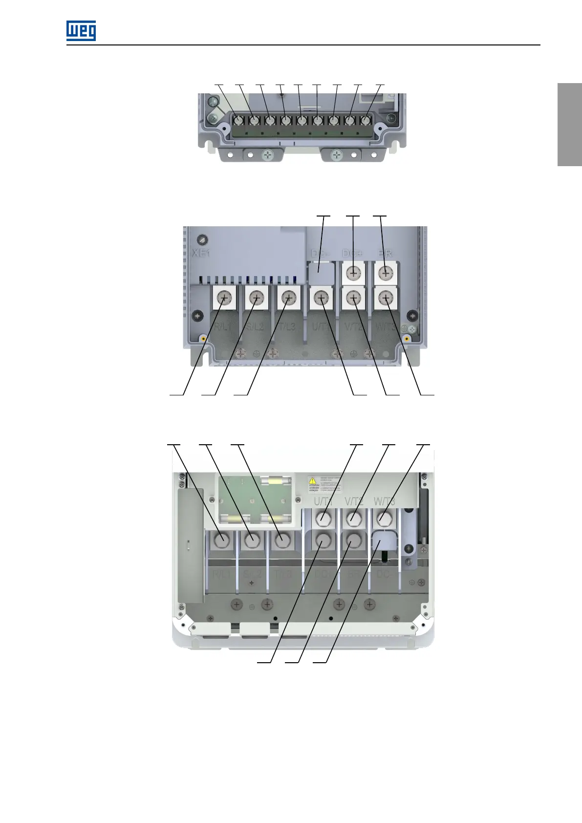
R/L1 S/L2 T/L3 DC- DC+BR U/T1 V/T2
W/T3
(a)FrameSizesA,BandC
R/L1 S/L2 T/L3 U/T1 V/T2 W/T3
BRDC+DC-
(b)FrameSizeD
R/L1 S/L2 T/L3 U/T1 V/T2 W/T3
(c)FrameSizeE
Figure3.9:Powerterminals
ToensuretheIP20protectionratinginframeCwhenpoweredbytheDClinkwithoutusingthebrakingresistor,
breaktheflapsofthecoverprotectingtheDC+,DC-andBRterminalsandinsertthisnewcovertosealtheBR
terminal,asshownin
Figure3.10.Inthiscase,thecoverofterminalsR/L1,S/L2andT/L3mustbekept.
CFW900|19