DTV 720 USER’S MANUAL
www.wegener.com 9 800043-01 Rev. C
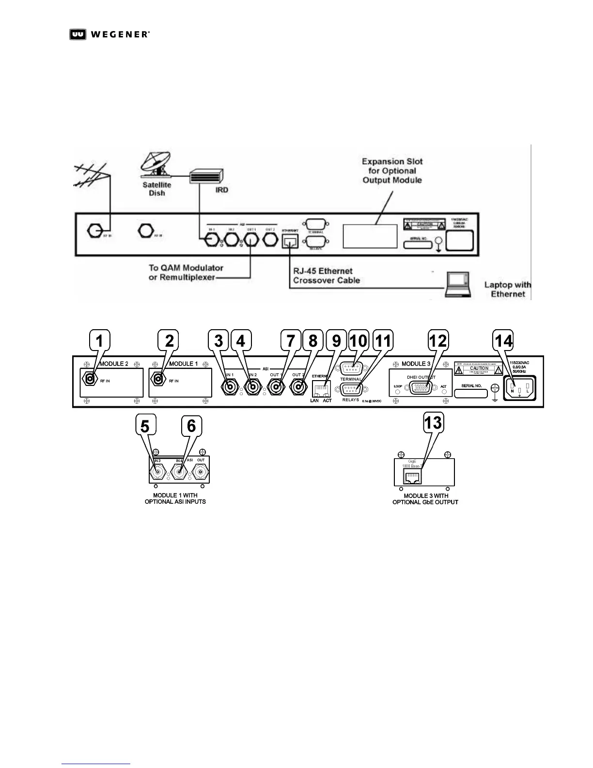
2.3 DTV 720 Connections
Figure 2.1: DTV 720 System Setup below shows placement of the DTV 720 in a typical cable
headend. Figure 2.2: DTV 720 Rear Panel Connections illustrates details of the DTV 720’s
rear panel.
Figure 2.1: DTV 720 System Setup
Figure 2.2: DTV 720 Rear Panel Connections
Before applying power, make the following connections to the DTV 720. (See Table2.1 for
the connector details.)
a. Connect the chassis grounding screw to an earth ground before connecting the
power cord to the unit.
b. Connect the 8VSB ATSC signal from your antenna to the RF IN port (1 and/or 2 if
present) and/or ASI input signals to the ASI IN 1 and ASI IN 2 ports (3 and 4).
c. If the Module 1 option with additional ASI input ports is installed, connect the ASI
IN 3 and ASI IN 4 ports (5 and 6, if present).
d. Connect downstream transmission or monitoring equipment to the ASI OUT 1 and
ASI OUT 2 ports (7 and 8) if present and desired.
e. Connect your LAN line to the DTV 720’s Ethernet port (9).
f. If desired, connect the Relays port (11) to your equipment to provide contact
closures during alarms and warnings.