DTV 720 USER’S MANUAL
800043-01 Rev.C 10 www.wegener.com
g. Connect the DHEI output connector (12, if present) to the cable headend DHEI
equipment using a 15-pin to 26-pin DHEI cable. Be sure to use the correct cable
depending upon whether you are connecting to the DHEI Expansion Input or the
DHEI Expansion Output connector.
h. Connect the GbE Output connector (13 if present) to an IP/Ethernet infrastructure.
Be sure to use good-quality CAT5E cable for this connection.
i. Finally, connect the supplied ac power cord to the DTV 720’s IEC receptacle (14)
and to a 90-to-132 Vac power source.
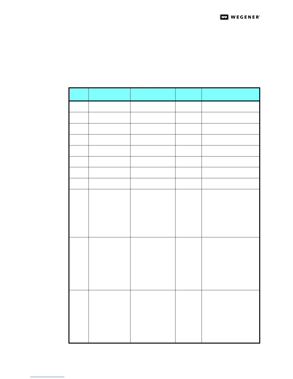
Table 2.1: DTV 720 Connector Details
Item Designation Connector Type Pin No. Signal Name
1 RF In 1 Female type-F RF IN 1
2 RF In 2 Ffemale type-F RF IN 2
3 ASI In 1 Female BNC ASI IN 1
4 ASI In 2 Female BNC ASI IN 2
5 ASI In 3 Female BNC ASI IN 3
6 ASI In 4 Female BNC ASI IN 4
7 ASI Out 1 Female BNC ASI OUT 1
8 ASI Out 2 Female BNC ASI OUT 2
9 Ethernet LAN Female RJ-45 1
2
3
4
5
6
7
8
EN OUT +
EN OUT -
EN IN +
NC
NC
EN IN -
NC
NC
10 Serial Async I/O DB-9 1
2
3
4
5
6
7
8
9
DCD (+5V, 4.7 kΩ)
RxD (output)
TxD (input)
NC
GND
DSR (+5V, 4.7 kΩ)
NC
CTS (+5V, 4.7 kΩ)
RI (+5V, 33 Ω)
11 Alarm/Warning
Relays
Male DB-9 1
2
3
4
5
6
7
8
9
Not used
Not used
WARNING COMMON
ALARM COMMON
GND
OPEN ON WARNING
OPEN ON ALARM
CLOSE ON WARNING
CLOSE ON ALARM