DTV 720 USER’S MANUAL
800043-01 Rev. C 14 www.wegener.com
LAN
Connection
For LAN connection, attach the DTV 720’s Ethernet port to the LAN using a normal,
straight-through, RJ-45 cable. Set the DTV 720 IP Address, Netmask, and Gateway as
directed by your network administrator. Use any PC on the LAN to connect to the DTV 720
using the web browser instructions below.
NOTE: Each DTV 720 unit on the network must have a unique address.
Using the
Web Browser
To begin DTV 720 monitor and control functions from a PC or LAN connection:
a. Open the current internet browser of your choice from the local PC or computer on
the LAN attached to your DTV 720.
b. Set the browser's address field to http://nnn.nnn.nnn.nnn where nnn.nnn.nnn.nnn
is the IP address of the unit to be controlled (set from the DTV 720’s front-panel, IP
Address screen).
NOTE: For IP addresses which include subfields with leading zeros, you must omit those
zeros when entering the address in your browser. For example, IP address
128.092.050.004 must be entered as 128.92.50.4.
The DTV 720 Control and Status page will appear. You may select the Stream Info, Unit
Configuration, Alarm Config, Pidsets Config, Module Config, or Q&A/Help pages at any time
by clicking the appropriate tab for each at the top of the screen.
Normally you will first select the Control & Status page to select the input, output, control,
and COMPEL characteristics. Use the Pidsets Config page to select programs to be
included in the output (by either channel name or program number), assign new program
numbers if desired, change the major/minor channel number, change the channel name,
and select the audio to be included in each program’s output. Next, select the Stream Info
page to verify that the input and output data are configured as intended
Finally, you may select the Unit Configuration screen to save the configuration. If you have
multiple configurations that you use from time to time, you may now set them up using the
same steps as above. After the initial setup, it will be easy to select various stored config-
urations from the Unit Configuration screen. The following paragraphs give a detailed
description of each screen.
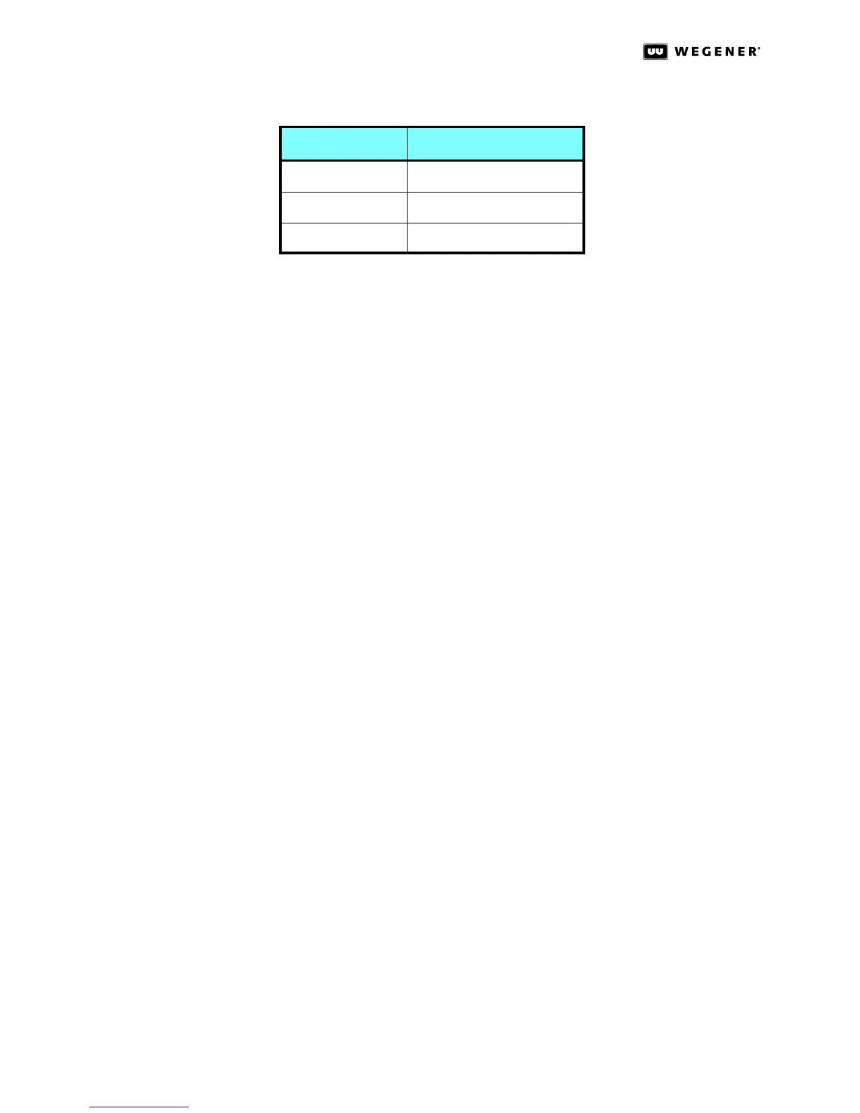
Table 3.2: PC IP Setup
Parameter Setting
IP Address 172.016.100.020
Netmask 255.255.000.000
Gateway 000.000.000.000