DTV 720 USER’S MANUAL
800043-01 Rev. C 28 www.wegener.com
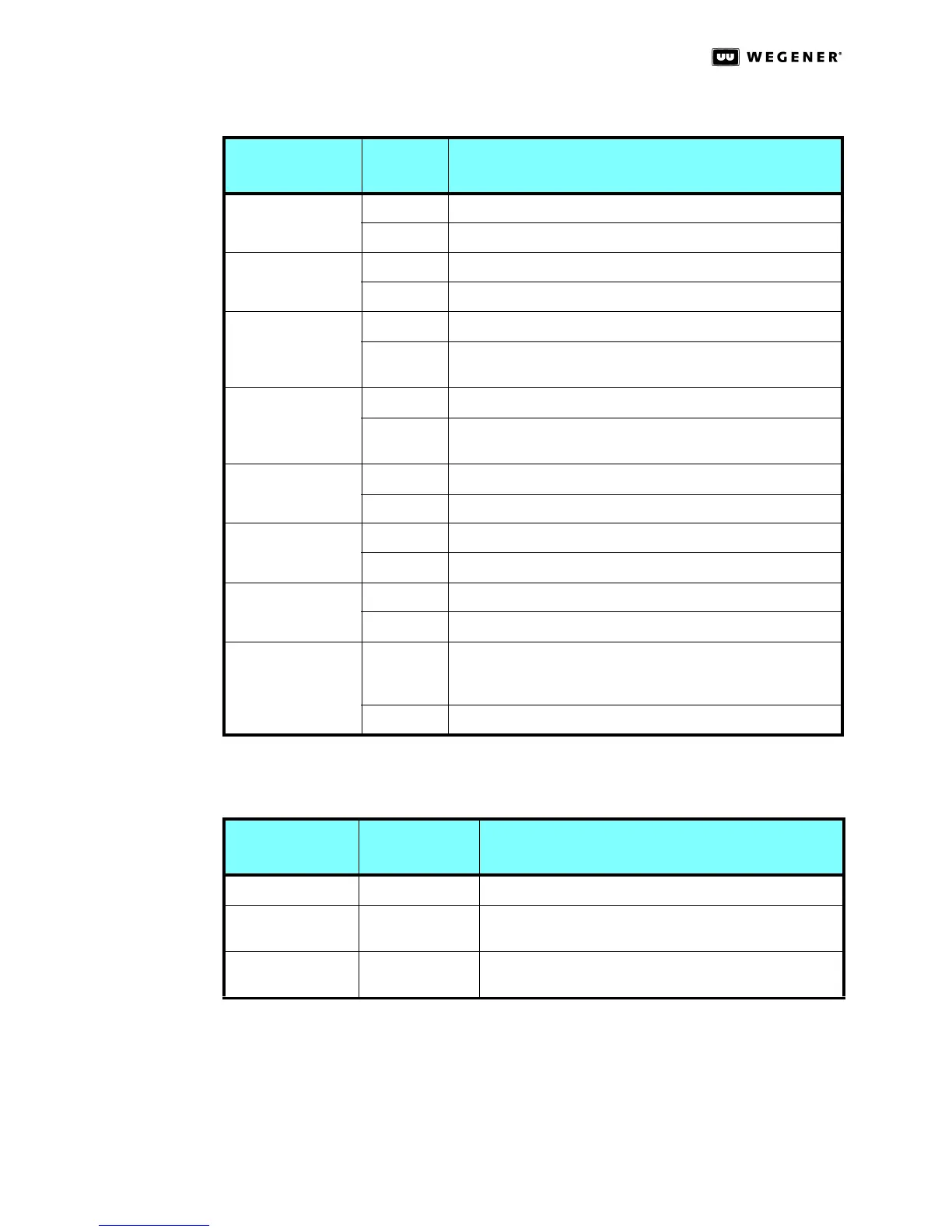
Rear Panel
LED
Indicators
Three LED indicators on the rear panel give Ethernet and ASI Input status:
Table 3.4: DTV 720 Front Panel LED Indicator Descriptions
Indicator
Label and Color
Indicator
State
Indicator Meaning
OPTION MOD 1
(Green)
Constant Option module 1 installed and operating
Off Option module 1 not installed or not operating
OPTION MOD 2
(Green)
Constant Option module 2 installed and operating
Off Option module 2 not installed or not operating
ASI 1 LOCK
(Green)
Constant ASI 1 input has Transport Stream synchronization present
Off ASI 1 input does not have Transport Stream
synchronization present
ASI 2 LOCK
(Green)
Constant ASI 2 input has Transport Stream synchronization present
Off ASI 2 input does not have Transport Stream
synchronization present
WARNING
(Yellow)
Constant Warning condition(s) exists
Off No Warning condition exists
ASI OUT LOCK
(Green)
Constant ASI Output is active
Off ASI Output is inactive
ALARM
(Red)
Constant Alarm condition(s) exists
Off No Alarm condition exists
LAN ACTIVITY
(Green)
Flash LAN activity present. Only lights when data is transferred to
the DTV 720. This is not a continuous monitor of LAN com-
munications.
Off No transfer of LAN data to the unit
Table 3.5: DTV 720 Rear Panel LED Indicator Descriptions
Indicator Label
Indicator Type
and Color Indicator Meaning
ACT LED: Ethernet activity blinks OFF and ON for activity detected
LAN
LED Ethernet rate indicator, OFF for 10baseT and ON for
100baseT
ASI Input
Red/Green LED OFF for not selected, RED for no input signal, GREEN for
input signal detected