DTV 720 USER’S MANUAL
800043-01 Rev. C 18 www.wegener.com
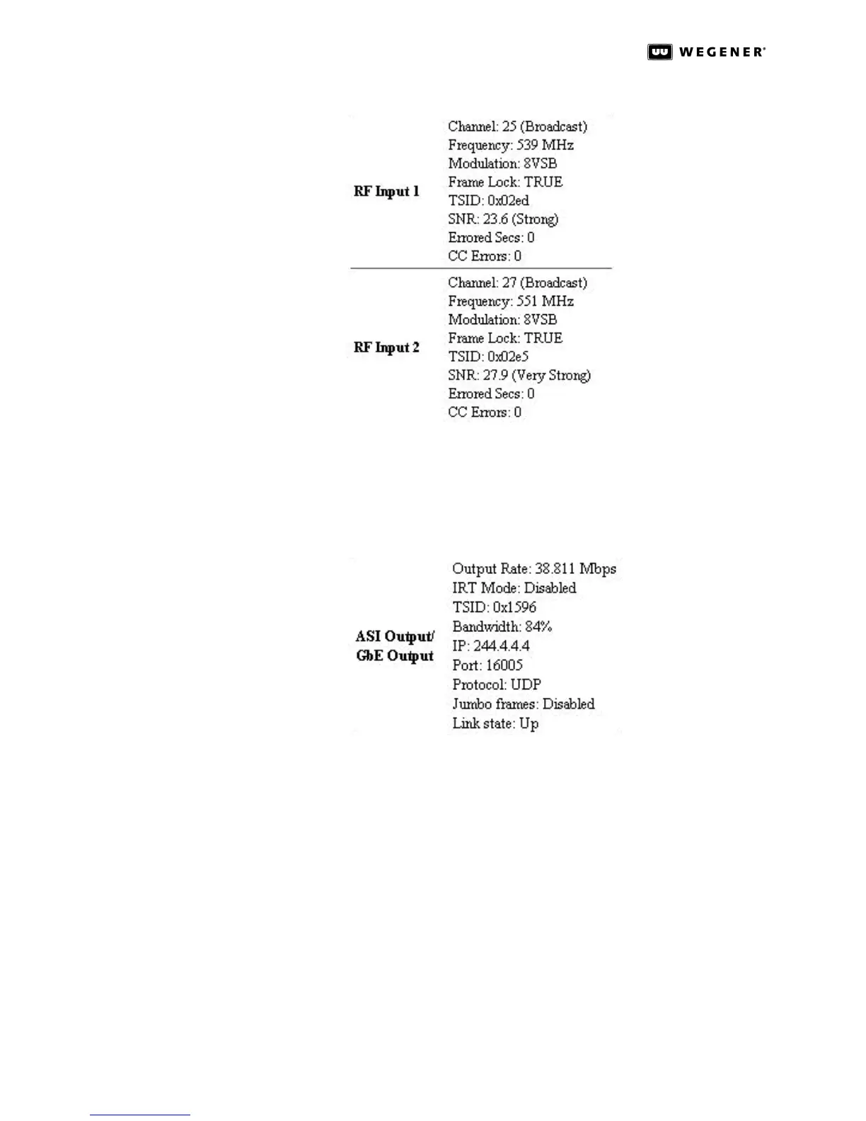
Figure 3.7: DTV 720 Control & Status Page RF Input Status
For each RF input, the RF Input entries show the Channel number (the actual RF broad-
cast channel, not the legacy analog channel number of the station); the Frequency; the
Modulation type (8VSB, 64QAM, or 256QAM); the Frame Lock status; the TSID; the SNR
(signal-to-noise ratio); the Errored Secs; and the CC Errors.
Figure 3.8: DTV 720 Control & Status Page ASI/GbE Output Status
ASI Output lists the ASI stream’s data transport Output Rate; IRT Mode status, TSID, and
Bandwidth utilization. Bandwidth indicates the percentage of the output Transport
Stream’s data rate that is occupied with actual data (not null packets).This indicator may
be used to determine whether additional programs may be enabled for output.
If the GbE Module is installed, the list will include the IP address; Port number; Protocol
type; Jumbo frames status; and output Link state.
If Compel is present and enabled, the Compel entry under Status indicates the Compel
source stream and the Compel PID. These should confirm the selections made under Com-
pel on the left side of the page. If Compel is not present and enabled, the entry will simply
show Disabled.