21Manual maxGUARD2526740000/02/03.2018
4 Conguration | Conguration in the Weidmüller Congurator
4 Conguration
4.1 CongurationintheWeidmüller
Congurator
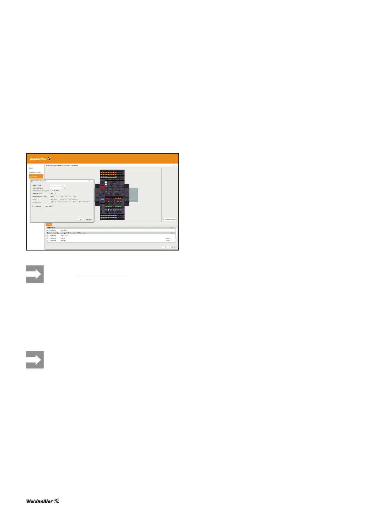
The Weidmüller Congurator helps you congure
maxGUARD stations and offers numerous import and export
functions for ECAD programs.
ConfigurationintheWeidmüllerConfigurator
You can download the Weidmüller Congurator
from the Weidmüller website.
4.2 Arrangement and combination of the
modules
A maxGUARD station always begins with a feed-in module,
followed by one or more separately selectable segments.
▶ Machine functions and load groups should be
grouped together as segments (see section
4.7).
W
e recommend arranging each segment of a maxGUARD
station from left to right in the following order:
– control module, if required
– load monitors and potential distribution terminals
– alarm module, if required
Feed-in modules
It is preferable to use passive feed-in modules in combination
with control modules. It is preferable to use active feed-in
modules for simple maxGUARD stations.
Feed-in modules should be positioned at the beginning of
a maxGUARD station and at the point where a station is ex-
tended (see section4.8).
All feed-in modules must be connected to both main strands.
Active feed-in modules must be connected to the internal
signal line. Control modules must not be connected to active
feed-in modules via the internal signal line.
Control modules
It is preferable to use control modules in conjunction with
passive feed-in modules.
Control modules should be positioned next to a passive feed-
in module or at the beginning of a segment.
Control modules must be connected to the internal signal
line and both main strands. Control modules must not be
connected to active feed-in modules via the internal signal
line.
Alarm modules
Alarm modules may only be used in conjunction with active
feed-in modules or with control modules.
Alarm modules may be positioned anywhere within a seg-
ment.
Alarm modules must be connected to the internal signal line
and both main strands.
Electronic load monitors
Electronic load monitors may only be used in conjunction
with feed-in modules.
Electronic load monitors may be positioned anywhere within
a segment.
Electronic load monitors must be connected to both main
strands.
If the electronic load monitors are to be controlled and moni-
tored by a control unit, they must be connected to an active
feed-in module or a control module via the internal signal
line.
Potential distribution terminals
Potential distribution terminals should be positioned directly
adjacent to the load monitor whose contacts are to be repli-
cated.
AMGPD,AMGOD,AMGMD,AMGDIS:
It is preferable to use these potential distribution terminals
with one-channel load monitors.
These potential distribution terminals must be connected to
the PLUS output or the MINUS output of the assigned elec-
tronic load monitors.
AMGXMD:
It is preferable to use this potential distribution terminal with
4-channel load monitors. Under no circumstances may it be
used with load monitors with a 2-pole output relay, as the
functional isolation at the MINUS output will be rendered
ineffective.
The AMGXMD must be connected to the GND main strand.