34Manual maxGUARD2526740000/02/03.2018
6 Electronicloadmonitors | AMG ELM-x...
6 Electronic load monitors
6.1 AMG ELM-x...
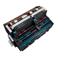
Left:AMGELM-6...
Right:AMGELM-12...
1 +24V main strand connection (+24V)
2 Thumbwheel switch
3 LED
4 Reset button “R”
5 PLUS output connection (cross-connector)
6 PLUS output connections (2.5mm
2
)
7 GND main strand connection (0V)
8 MINUS output connections (2.5mm
2
)
9 MINUS output connection (cross-connector)
10 Markers
11 Internal signal line connection
The AMGELM-6 and AMGELM-12 electronic load moni-
tors monitor individual load circuits and disconnect them in
the event of a short circuit or overload. The tripping current
and the tripping characteristic are selected using the thumb-
wheel switch.
LED Colour Meaning
LED
Green Fault-free operation
Red Load monitor is switched off
Red, ashing Load monitor tripped
Red, ashing fast Internal error
Orange (red and green) Overtemperature detected
Red, green, alternating Reset button deactivated for 30 seconds
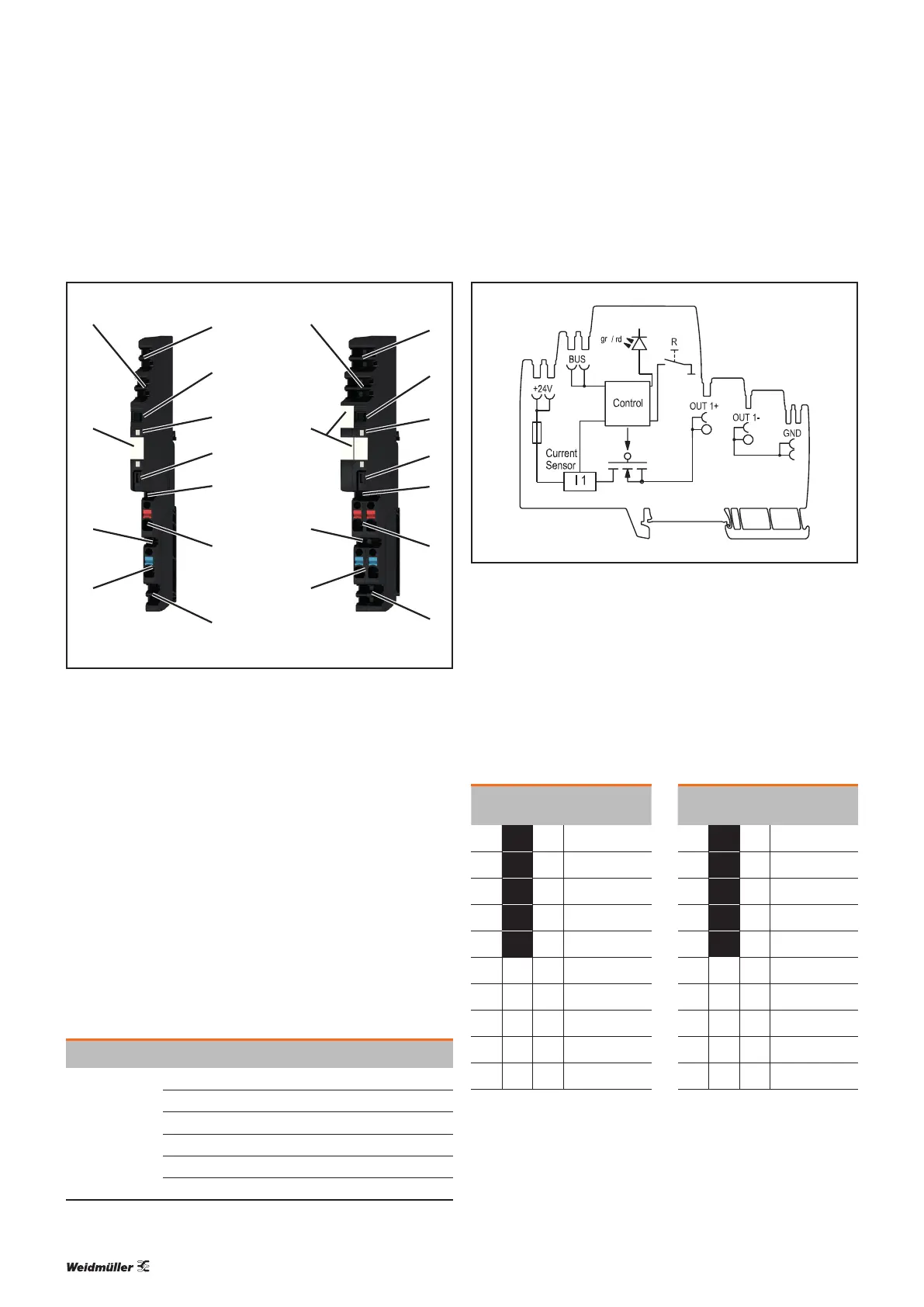
AMG ELM-6..., AMG ELM-12... block diagram
The reset button “R” can be used to individually reset and
switch on/off the load monitors.
The thumbwheel switch has ten settings. The current values
of the standard tripping characteristic are shown with white
numbers on a black background. The current values of the
delayed tripping characteristic are shown with black num-
bers on a white background.
AMG ELM-6... AMG ELM-12...
Thumbwheel
switch
Characteristic Thumbwheel
switch
Characteristic
1
1A
N
4
4A
N
2
2A
N
6
6A
N
3
3A
N
8
8A
N
4
4A
N
10
10A
N
6
6A
N
12
12A
N
1
1A
T
4
4A
T
2
2A
T
6
6A
T
3
3A
T
8
8A
T
4
4A
T
10
10A
T
6
6A
T
12
12A
T