To this end, only the ZQV4N/x cross-connectors specied in
section
3.6 shall be used.
Whenever possible, use uncut cross-connectors insulated on
both sides. Cut cross-connectors may only be used if cross-
connectors with more than ten poles are required.
If cut cross-connectors are used for the load outputs or the
internal signal line, the bare cut edges must be insulated
against short circuits with separation plates.
The individual contact elements of the cross-connectors do
not need to be removed. If a module cannot be connected
to a specic main connection channel, the corresponding
cross-connection contacts will not be available. Installed
cross-connectors will subsequently not be connected to the
module.
The block diagrams of the individual modules
show the active cross-connection contacts. The
respective block diagram is printed on the side of
the module (see chapters 5 to 7).
The use of different-coloured cross-connectors simplies as-
sembly and enhances the clarity of the maxGUARD station.
▶ Cut the 50-pole cross-connectors to the required length
using the cutting tool.
▶ Install the cross-connectors in accordance with the instal-
lation drawing or wiring diagram.
8.5 Wiring
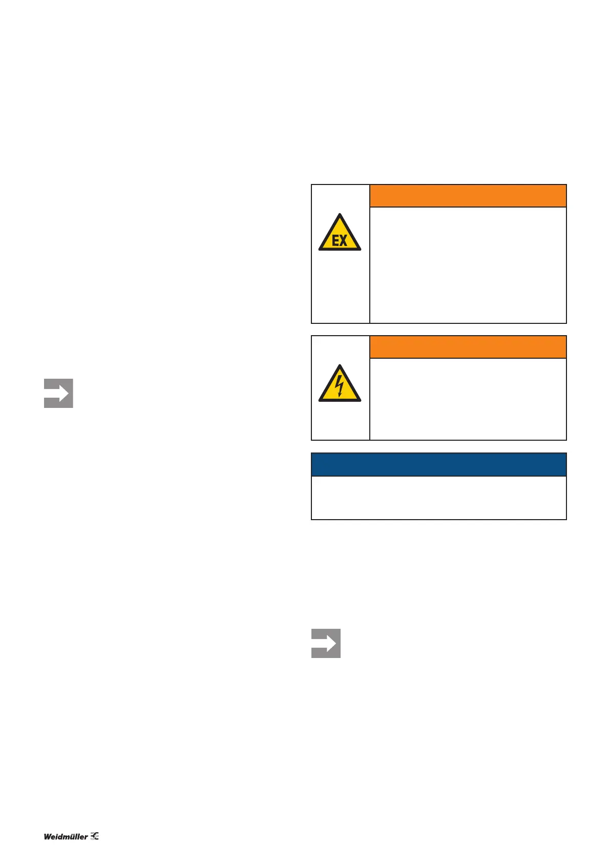
WARNING
Explosion risk!
▶ Before starting any work, make sure that
there is not a potentially explosive atmos-
phere!
▶ For applications in explosive risk zones,
observe the installation and construction
requirements of EN60079-15 and/or
country-specific regulations.
WARNING
Dangerous contact voltage!
▶ Carry out installation and wiring work on
the maxGUARD station only when the
power supply is disconnected.
▶ Make sure that the place of installation
(panel etc.) has been disconnected from
the power supply!
ATTENTION
Risk of destruction if polarity is incorrect!
▶ Connect devices with the correct polarity.
▶ Check that all connecting lines are firmly in place.
Once the maxGUARD station has been mechanically in-
stalled and all cross-connectors have been correctly tted,
the wiring can be carried out in accordance with the wiring
diagram.
Only copper conductors with a suitable cross-section may be
connected.
The wire cross-sections must be measured ac-
cording to the internal fuse value, not the tripping
current of the electronic load monitor (see sec-
tion3.5).
51Manual maxGUARD2526740000/02/03.2018
8 Installationandwiring | Wiring