36Manual maxGUARD2526740000/02/03.2018
6 Electronicloadmonitors | AMGELM-xF...
6.2 AMGELM-xF...
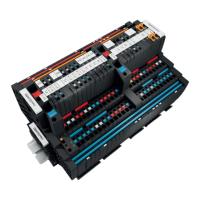
Left:AMGELM-1F...,AMGELM-2F...,AMGELM-4F...,AMGELM-6F...
Right:AMGELM-8F...,AMGELM-10F...
1 +24V main strand connection (+24V)
2 LED
3 Reset button “R”
4 PLUS output connection (cross-connector)
5 PLUS output connections (2.5mm
2
)
6 GND main strand connection (0V)
7 MINUS output connections (2.5mm
2
)
8 MINUS output connection (cross-connector)
9 Markers
10 Internal signal line connection
The AMGELM-1F to AMGELM-10F 1-channel electronic
load monitors monitor individual load circuits and disconnect
them in the event of a short circuit or overload. The tripping
current and the tripping characteristic are xed.
LED Colour Meaning
LED
Green Fault-free operation
Red Load monitor switched off
Red, ashing Load monitor tripped
Red, ashing fast Internal error
Red, green, alternating Reset button deactivated for 30 seconds
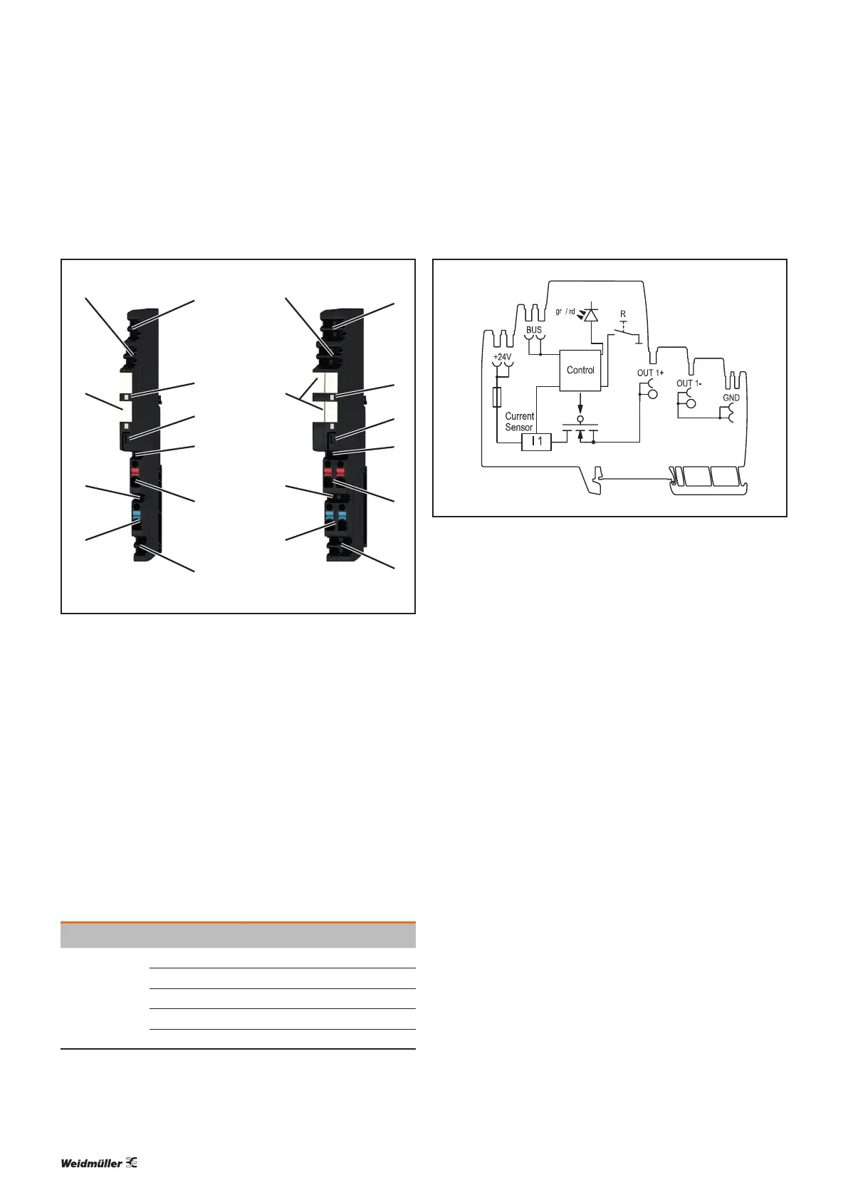
AMG ELM--xF... block diagram
The reset button “R” can be used to individually reset and
switch on/off the load monitors.