29Manual maxGUARD2526740000/02/03.2018
4 Conguration | Example congurations
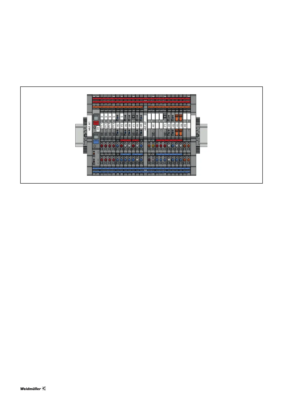
Example: Two segments with connection to a control unit
Example: maxGUARD station with two segments and connection to a control unit
This example shows a control voltage distributor with two
segments for seven selectively fused load circuits with con-
nection to a control unit.
The following maxGUARD products are used:
– 1xAMGFIM-C
– 1xAMGCM
– 1xAMGAM
– 1xAMGELM-6
– 1xAMGELM-4F
– 1xAMGELM-Q2222
– 1xAMGELM-10D-C0
– 2xAMGPD
– 2xAMGOD
– 2xAMGMD
– 1xAMGXMD
– 2xAMGDIS
– 1xAMGPP
– 2xAMGEP
– 2xWEW35/2
– 1xZQV4N/50RD, 1xZQV4N/3RD, 1xZQV4N/2RD,
1xZQV4N/7RD
– 1xZQV4N/50
– 1xZQV4N/50BL, 2xZQV4N/3BL, 1xZQV4N/7BL
The active feed-in module feeds in the supply voltage and
connects the rst segment to the control unit. The second
segment is connected to the control unit via the control mod-
ule and the alarm module.
The potentials are distributed to the individual modules via
cut cross-connectors. Since the total current owing through
the station is greater than 20A, the main strands are each
equipped with two cross-connectors. The internal signal line
is established via two cut cross-connectors which connect
the modules within the segments.
The outputs of the load monitors are replicated using poten-
tial distribution terminals. The potential distribution terminals
are connected to the outputs of the load monitors via uncut
cross-connectors.
The station must be equipped with end plates at both
ends. Only then will the exposed cut edges of the cut cross-
connectors be insulated. The separation plate divides the
segments and prevents short circuits at the non-insulated cut
edges of the cross-connectors for the internal signal lines.