1.
PC
:Pull-in Coil
2.
HC
:Holding Coil
3. S :Switch
4. Drive Lever
clutch
5. Screw Spline
6. Armature
7.
Pole Core
8. Commutator
9. Contact Plate
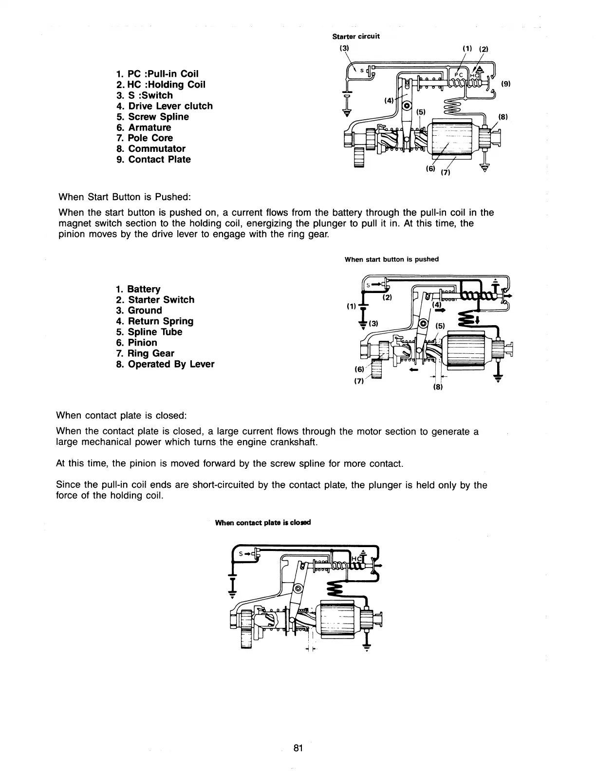
When Start Button is Pushed:
Starter
circuit
(3)
(1) (2)
When the start button is pushed on, a current flows from the battery through the pull-in coil
in
the
magnet switch section to the holding coil, energizing the plunger to pull it in. At this time, the
pinion moves
by
the drive lever to engage with the ring
gear.
When start button is pushed
1. Battery
2. Starter Switch
3.
Ground
4.
Return Spring
5.
Spline Tube
6.
Pinion
7.
Ring Gear
8.
Operated By Lever
When contact plate is closed:
When the contact plate is closed, a large current flows through the motor section to generate a
large mechanical power which turns the engine crankshaft.
At
this time, the pinion is moved forward
by
the screw spline for more contact.
Since the pull-in coil ends are short-circuited
by
the contact plate, the plunger is held only
by
the
force of the holding coil.
When
contact
plate
il
clo'"
81