176 www.xilinx.com 7 Series FPGAs GTP Transceivers User Guide
UG482 (v1.9) December 19, 2016
Chapter 4: Receiver
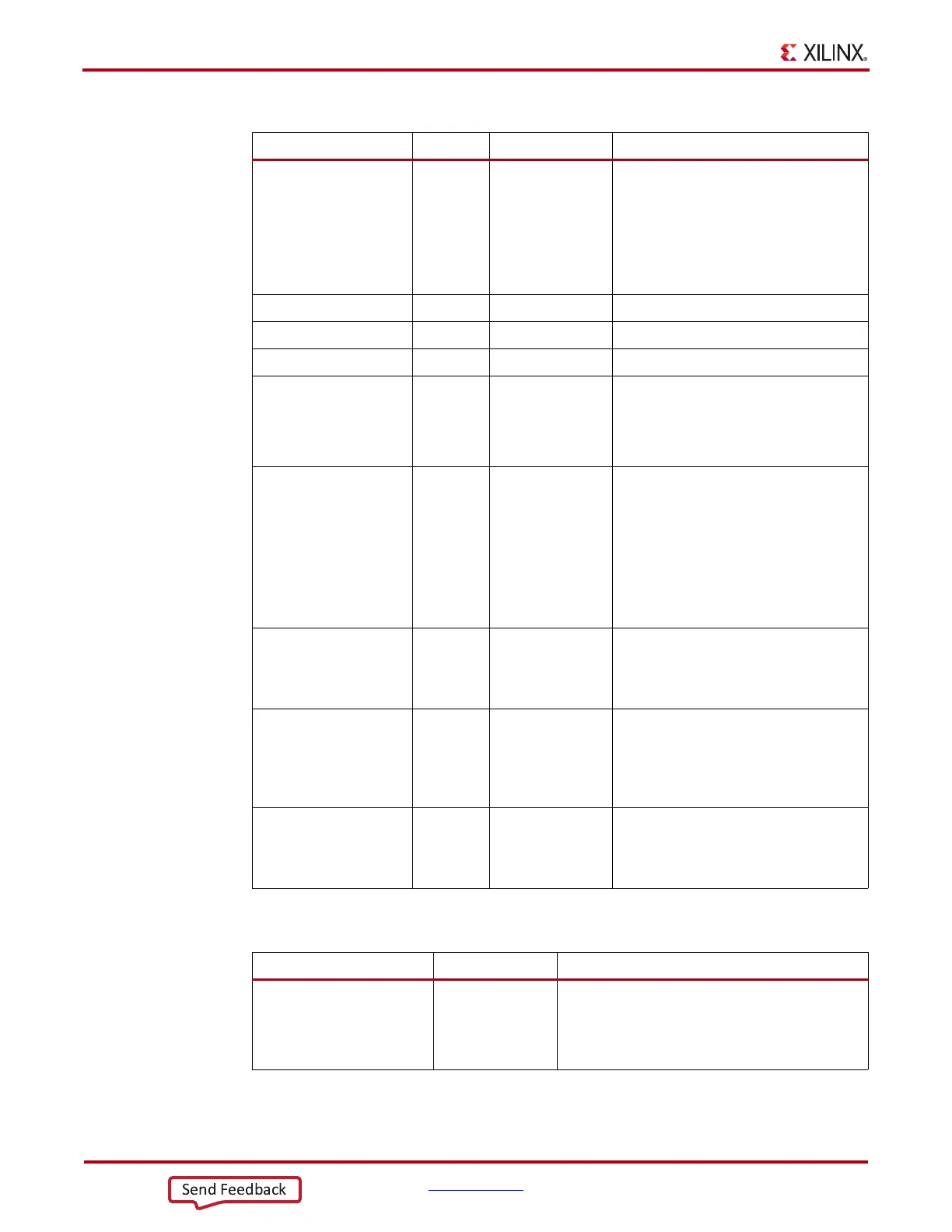
Table 4-30 defines the RX buffer attributes.
RXPHALIGNDONE Out Async RX phase alignment done. When the auto
RX phase and delay alignment are used,
the second rising edge of
RXPHALIGNDONE detected after
RXDLYSRESETDONE assertion
indicates RX phase and delay alignment
are done.
RXPHMONITOR Out Async RX phase alignment monitor.
RXPHSLIPMONITOR Out Async RX phase alignment slip monitor.
RXDLYSRESETDONE Out Async RX delay alignment soft reset done.
RXSYNCMODE In Async 0: RX Buffer Bypass Slave lane
1: RX Buffer Bypass Master lane
This input is not used in multi-lane
manual mode.
RXSYNCALLIN In Async Single-lane auto mode: Connect this
input to its own RXPHALIGNDONE.
Multi-lane auto mode: Connect this input
to the ANDed signal of
RXPHALIGNDONE of the master and
all slave lanes.
Multi-lane manual mode: This input is
not used in multi-lane manual mode.
RXSYNCIN In Async Only valid in multi-lane auto mode
applications. Connect this input to
RXSYNCOUT from RX buffer bypass
master lane.
RXSYNCOUT Out Async Only valid for RX buffer bypass master
lane in multi-lane auto mode
applications. Connect this signal to the
RXSYNCIN of each lane within the
multi-lane application.
RXSYNCDONE Out Async Indicates RX Buffer Bypass alignment
procedure completion. Only valid for RX
buffer bypass master lane in auto mode
operation.
Table 4-30: RX Buffer Bypass Attributes
Attribute Type Description
RXBUF_EN String Use or bypass the RX elastic buffer.
TRUE: Uses the RX elastic buffer (default).
FALSE: Bypasses the RX elastic buffer
(advanced feature).
Table 4-29: RX Buffer Bypass Ports (Cont’d)
Port Dir Clock Domain Description