7 Series FPGAs GTP Transceivers User Guide www.xilinx.com 223
UG482 (v1.9) December 19, 2016
Pin Description and Design Guidelines
Unused GTP Quad Power Supply Group
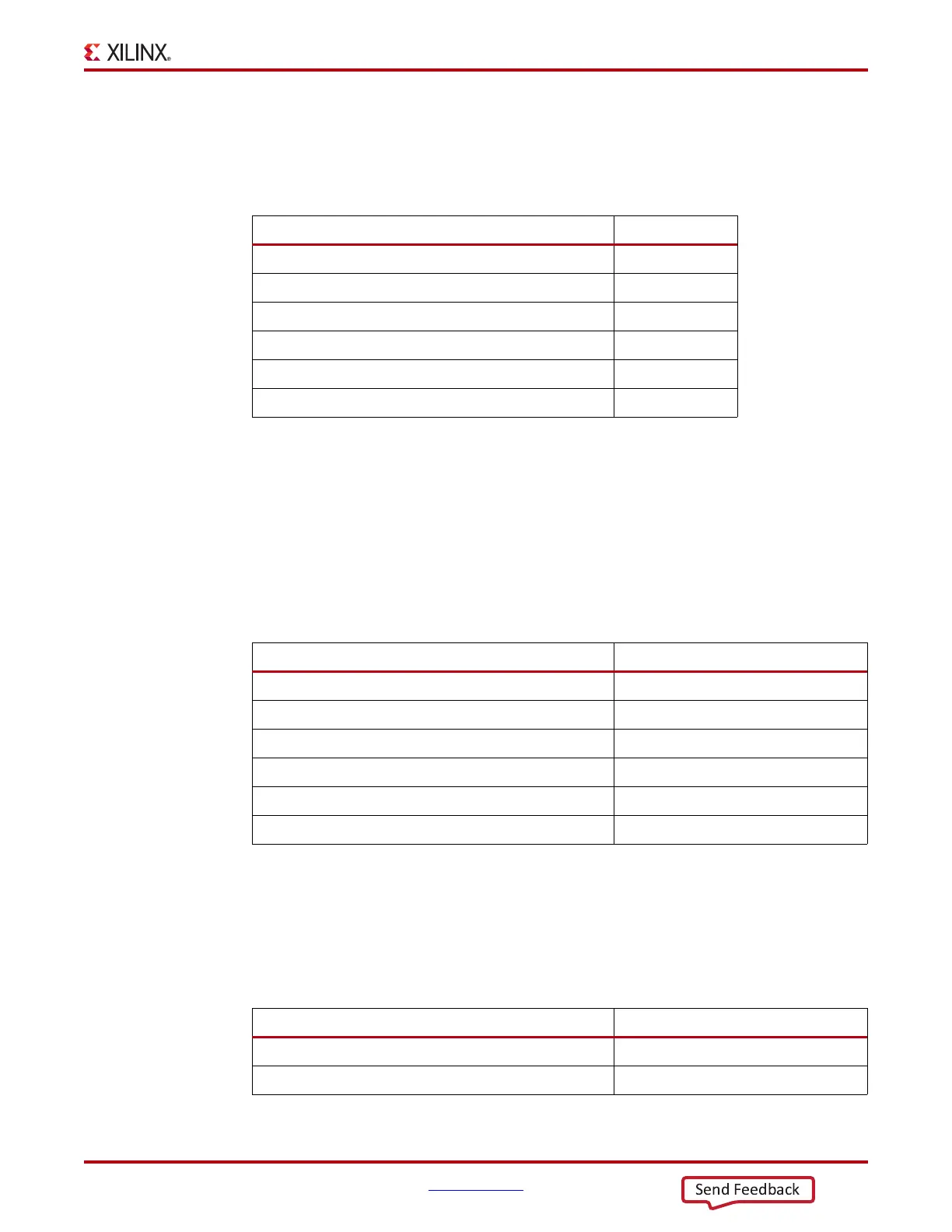
If none of the GTP Quads in a power supply group are used in the application, the GTP Quad device
pins can be connected as shown in Table 5-4.
Partially Unused GTP Quad Power Supply Group
If only a portion of the GTP Quads in a power supply group is used, the pins for unused GTP Quads
must be connected as shown in Table 5-5. Notice for this case, the power supply pins must be
connected to the appropriate power supply operating voltage and the MGTRREF pin is connected to
MGTAVTT through a 100Ω resistor.
Partially Used GTP Quad
There are four GTP Transceivers in an Artix-7 FPGA GTP Quad. For a partially used GTP Quad
where one or more but not all of the transceivers are not used, the analog power supplies,
MGTAVCC and MGTAVTT, need to be connected. Table 5-6 shows the connections to the Quad for
the GTP transceivers that are not used.
Table 5-4: Unused GTP Quad Column Connections
Pin or Pin Pair of the Unused GTP Quad Connection
MGTAVCC GND
MGTAVTT GND
MGTREFCLKP/MGTREFCLKN Float
MGTRXP/MGTRXN GND
MGTTXP/MGTTXN Float
MGTRREF
(1)
GND
Notes:
1. This is the only scenario when the MGTRREF pins can be connected to ground. In all
other scenarios, these pins must be connected for normal operation.
Table 5-5: Unused GTP Quad Column Connections
Pin or Pin Pair of the Unused GTP Quad Connection
MGTAVCC AVCC
MGTAVTT AVTT
MGTREFCLKP/MGTREFCLKN Float
MGTRXP/MGTRXN GND
MGTTXP/MGTTXN Float
MGTRREF MGTAVTT through a 100Ω resistor
Table 5-6: Unused GTP Quad Column Connections
Pin or Pin Pair of the Unused GTP Quad Connection
MGTAVCC AVCC
MGTAVTT AVTT