236 www.xilinx.com 7 Series FPGAs GTP Transceivers User Guide
UG482 (v1.9) December 19, 2016
Chapter 5: Board Design Guidelines
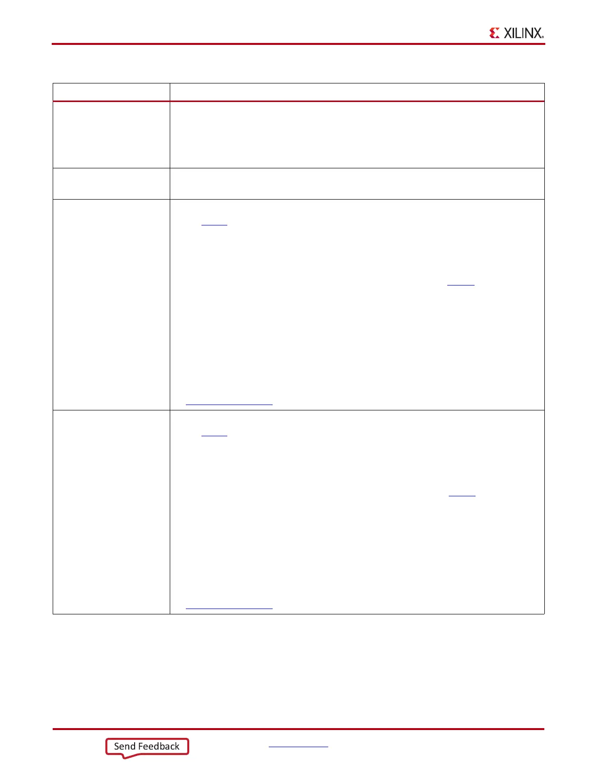
MGTTXP0/MGTTXN0
MGTTXP1/MGTTXN1
MGTTXP2/MGTTXN2
MGTTXP3/MGTTXN3
• Transmitter should be AC coupled to the receiver. The recommended value for the AC coupling
capacitors is 100 nF.
• Transmitter data traces should be provided enough clearance to eliminate crosstalk from adjacent
signals.
• If a transmitter is not used leave the associated pin pair unconnected.
MGTRREF • Connect to a 100Ω resistor that is also connected to MGTAVTT.
•See Termination Resistor Calibration Circuit, page 219.
MGTAVCC_G[N] • The nominal voltage is 1.0 VDC.
•See DS181
, Artix-7 FPGAs Data Sheet: DC and Switching Characteristics for power supply
voltage tolerances.
• The power supply regulator for this voltage should not be shared with non-transceiver loads.
• Many packages have multiple groups of power supply connections in the package for
MGTAVCC. Refer to
Table 5-2 to identify in which power supply group a specific GTP Quad is
located. Information on pin locations for each package can be found in UG475, 7 Series FPGAs
Packaging and Pinout Specifications.
• The following sets of ceramic filter capacitors for each power supply group are recommended:
• 1 of 4.7 µF 10%
• 2 of 0.1 µF 10%
• For optimal performance, power supply noise must be less than 10 mV
PK-PK
.
• If all of the Quads in a power supply group are not used, the associated power pins can be tied to
ground.
• For power consumption refer to the XPower Estimator (XPE) for 7 series devices at
www.xilinx.com/power
.
MGTAVTT_G[N] • The nominal voltage is 1.2 VDC.
•See DS181
, Artix-7 FPGAs Data Sheet: DC and Switching Characteristics for power supply
voltage tolerances.
• The power supply regulator for this voltage should not be shared with non-MGT loads.
• Many packages have multiple groups of power supply connections in the package for
MGTAVTT. Refer to
Table 5-2 to identify in which power supply group a specific GTP Quad is
located. Information on pin locations for each package can be found i in UG475
, 7 Series FPGAs
Packaging and Pinout Specifications.
• The following set of ceramic filter capacitors for each power supply group are recommended:
• 1 of 4.7uF 10%
•
2 of 0.1 µF 10%
• For optimal performance power supply noise must be less than 10 mV
PK-PK
.
• If all of the Quads in a power supply group are not used the associated power pins can be tied to
ground.
• For power consumption refer to XPower Estimator (XPE) for 7 series devices at
www.xilinx.com/power
.
Table 5-14: GTP PCB Design Checklist (Cont’d)
Pins Recommendations