3. The associated PLL must indicate locked.
4. The guideline for this asynchronous GTTXRESET pulse width is one period of the reference
clock.
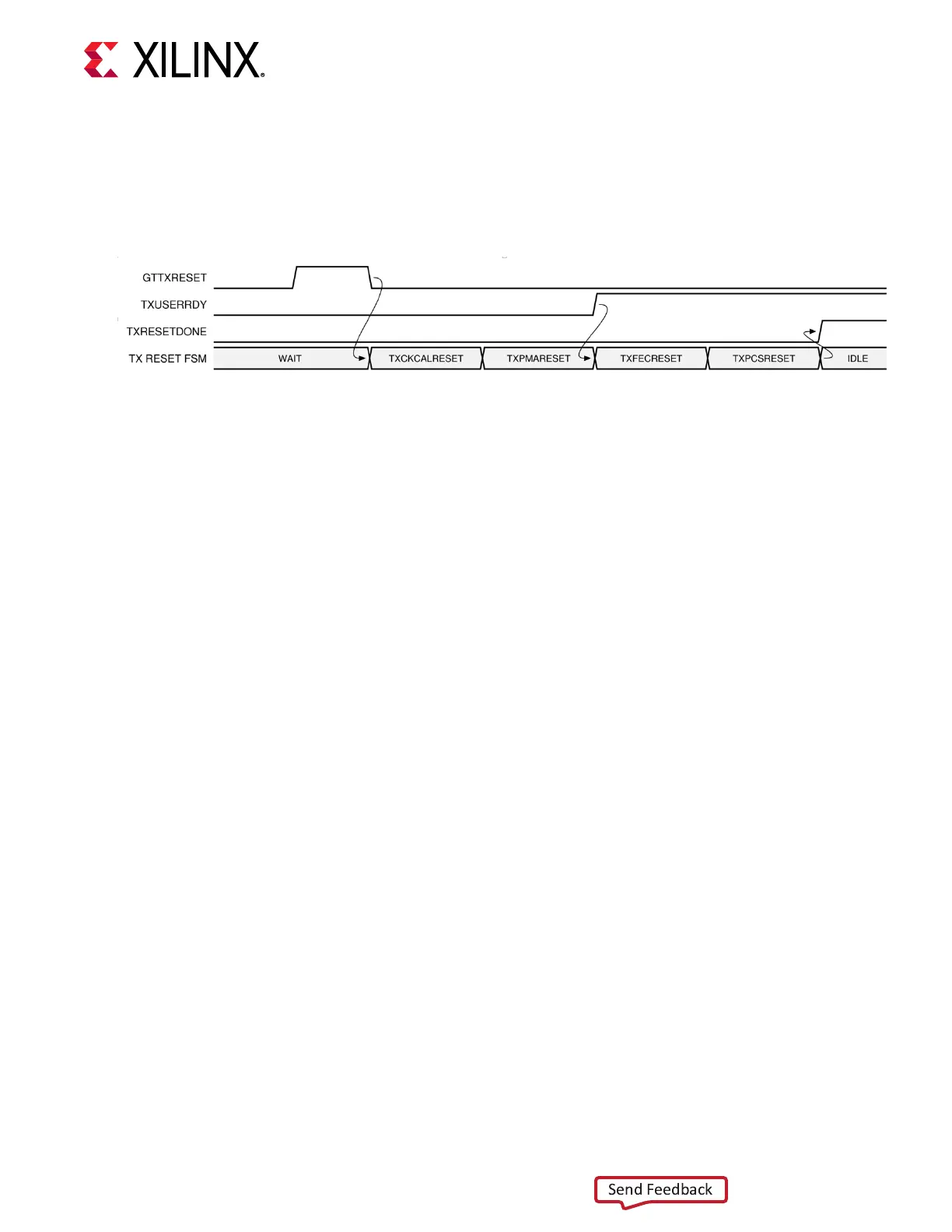
Figure 15: GTM Transmitter Reset after GTTXRESET Pulse in Full Sequential Reset
GTM Transceiver TX Component Reset
TX PMA and TX PCS can be reset individually. Component reset is enabled by seng the
appropriate TXPMARESETMASK and TXPCSRESETMASK bits along with TXRESETMODE and
then toggling GTTXRESET.
Driving GTTXRESET from High to Low starts the component reset process. All
TXPMARESETMASK and TXPCSRESETMASK bits along with TXRESETMODE must be held
constant during the reset process.
When TXRESETMODE is set to sequenal mode, the internal resets are toggled in sequence
depending on TXPMARESTMASK and TXPCSRESETMASK selecon. When TXRESETMODE is
set to single mode, the internal resets are toggled simultaneously depending on
TXPMARESETMASK and TXPCSRESTMASK selecon.
In sequenal mode, if the TX PCS is to be reset, TXUSERRDY must toggle to High prior to the
internal PCS reset signal being released allowing TX reset to be completed.
Direct single-reset ports TXPMARESET, TXCKALRESET, TXPCSRESET, and TXFECRESET are
available to perform single resets of the respecve TX components. When direct single-reset
ports are toggled, a single reset is performed regardless of TXPMARESETMASK,
TXPCSRESETMASK, and TXRESETMODE selecon. These ports must be held Low during any
sequenal or single resets driven by GTTXRESET.
Chapter 2: Shared Features
UG581 (v1.0) January 4, 2019 www.xilinx.com
Virtex UltraScale+ GTM Transceivers 31
 Loading...

