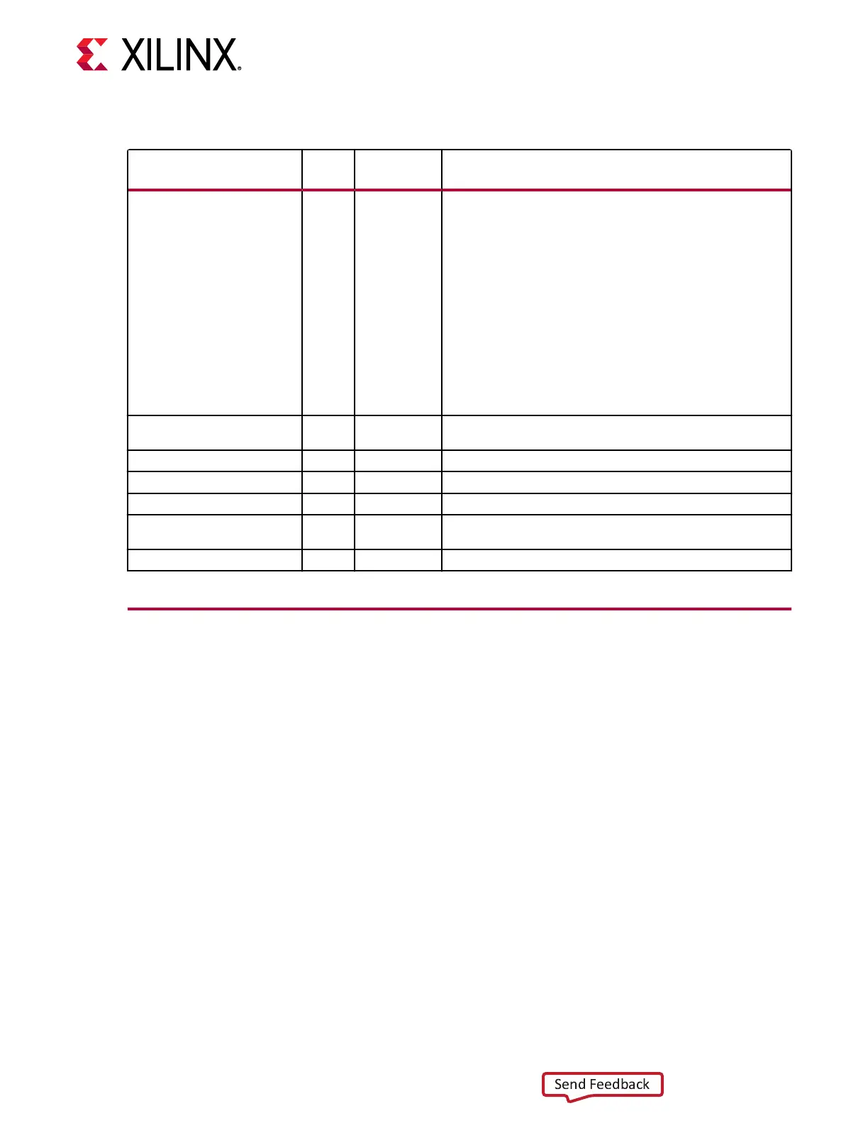
Table 7: GTM_DUAL Clocking Ports
Port
Direct
ion
Clock
Domain
Description
PLLREFCLKSEL[2:0] In Async Input to dynamically select the input reference clock to the
LCPLL. Set this input to 3’b001 and connect to GTREFCLK when
only one clock source is connected to the PLL reference clock
selection multiplexer:
3’b000: Reserved.
3’b001: GTREFCLK selected.
3’b010: Reserved.
3’b011: GTNORTHREFCLK selected.
3’b100: Reserved.
3’b101: GTSOUTHREFCLK.
3’b110: Reserved.
3’b111: GTGREFCLK2PLL.
GTGREFCLK2PLL In Clock Reference clock generated by the internal interconnect logic.
This input is reserved for internal testing purposes only.
GTREFCLK In Clock External clock driven by IBUFDS_GTM for the LCPLL.
GTNORTHREFCLK In Clock Northbound clock from the Dual below.
GTSOUTHREFCLK In Clock Southbound clock from the Dual above.
PLLREFCLKLOST Out Async A High on this signal indicates that the reference clock to the
phase frequency detector of the LCPLL is lost.
PLLREFCLKMONITOR Out Clock LCPLL reference clock selection multiplexer output.
LCPLL
Each Dual contains one LC-based PLL, referred to as LCPLL, and cannot be shared with
neighboring Duals. The internal clocking architecture of the GTM Dual is shown in the following
gure.
Chapter 2: Shared Features
UG581 (v1.0) January 4, 2019 www.xilinx.com
Virtex UltraScale+ GTM Transceivers 18
 Loading...

