Chapter 3
Transmitter
This chapter shows how to congure and use each of the funconal blocks inside the transmier
(TX). Each transceiver includes an independent transmier, which consist of a PCS and a PMA.
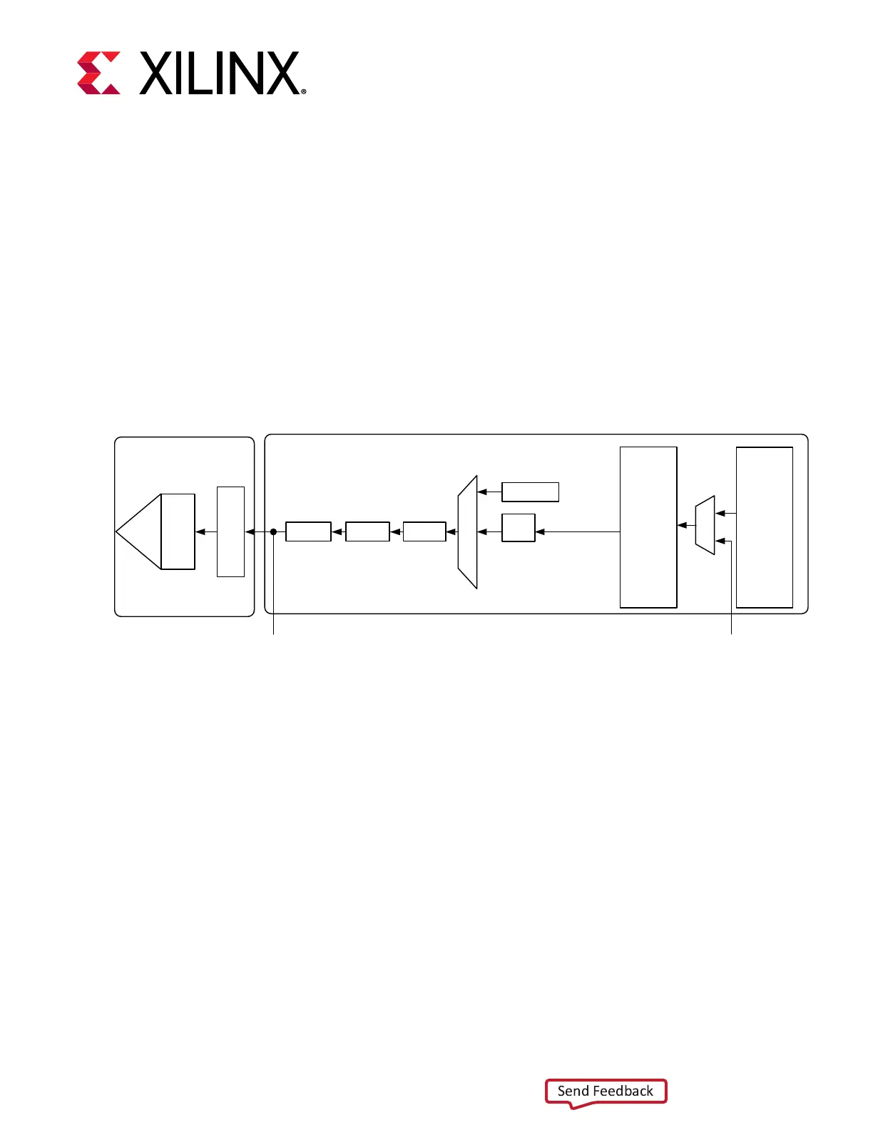
The following gure shows the funconal blocks of the transmier. Parallel data ows from the
device logic into the TX interface through the PCS and PMA, and then out the TX driver as high-
speed serial data.
Figure 24: GTM Transceiver TX Block Diagram
Pattern
Generator
Polarity
FIFO
To RX Parallel
Data (Near-End
PCS Loopback)
From RX Parallel
Data (Far-End
PCS Loopback)
TX
Interface
FEC
Gray
Encoder
Pre-
Coder
TX PCS
PIS
O
TX
Driver
TX
Pre/
Pre2/
Post
Emp
TX PMA
X20910-052818
The key elements within the GTM transceiver TX are:
1. TX Interface
2. TX FEC
3. TX Buer
4. TX Paern Generator
5. TX Polarity Control
6. TX Gray Encoder
7. TX Pre-Coder
8. TX Fabric Clock Output Control
9. TX Congurable Driver
Chapter 3: Transmitter
UG581 (v1.0) January 4, 2019 www.xilinx.com
Virtex UltraScale+ GTM Transceivers 54
 Loading...

