xiC - Technical Manual Version 1.16
3.7. xiC USB 3.1 Gen1 Type-C Interface
Standard USB 3.1 Gen1 Type-C Connector
Standard USB 3.1 Type C Connector with thumbscrews
Screw thread M2, thread distance 15.0mm
table 3-24, USB 3.1 mating connector description
The USB 3.1 Type C connector is used for data transmission, camera control and power.
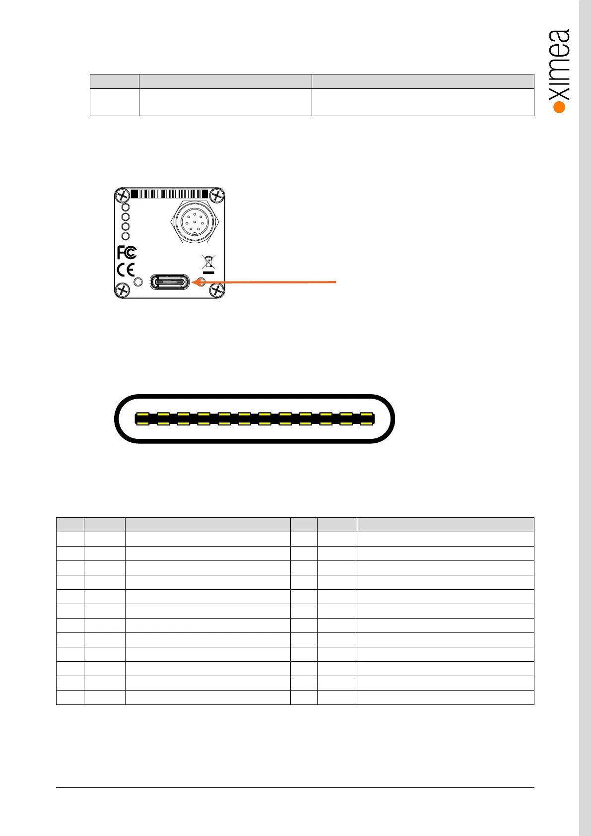
3.7.1. Type-C connector location
figure 3-32, position of Type-C connector
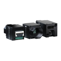
3.7.2. Pinning
figure 3-33 pinning of Type-C connector
SuperSpeed differential pair #1, TX, pos.
SuperSpeed differential pair #2, RX, pos.
SuperSpeed differential pair #1, TX, neg.
SuperSpeed differential pair #2, RX, neg.
Non-SuperSpeed diff. pair, position 1, pos.
Non-SuperSpeed diff. pair, position 2, neg.
Non-SuperSpeed diff. pair, position 1, neg.
Non-SuperSpeed diff. pair, position 2, pos.
SuperSpeed differential pair #4, RX, neg.
SuperSpeed differential pair #3, TX, neg.
SuperSpeed differential pair #4, RX, pos.
SuperSpeed differential pair #3, TX, pos.
Table 3-25 USB type C connector pin assignment
xiC
1
2
3
4
MC023CG-SY-TC
CACAC1623001
Made in SK
IO
AUX
power
USB 3.1 Gen 1
Type C
Type-C
A1 A2 A3 A4 A5 A6 A7 A8 A9 A10 A11 A12
B12 B1B2B3B4B5B6B7B8B9B10B11