xiC - Technical Manual Version 1.16
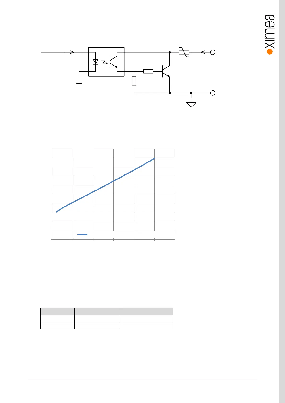
3.10.4.3. Optically isolated Digital Output – Internal schematic
Following scheme is the internal scheme of the Digital Output signal flow inside the camera.
figure 3-47, digital output, interface schematic
Output Transfer Characteristic
When Output is in On state - typical transfer characteristic of output is as on following figure:
figure 3-48, digital output transfer characteristics
3.10.4.4. Digital Output – Wiring
Digital output has an open collector switching transistor with common IO Ground. In most cases a power source for external
device must be provided.
3.10.4.4.1. Connecting Digital OUTPUT to a NPN-compatible PLC device input (biased)
PTC Fuse
FPGA_OUTPUT
GND
10K
1K
DIGITAL OUTPUT
GND (Common IO Ground)
Idrive=2mA
I
LOA D
0.0
0.2
0.4
0.6
0.8
1.0
1.2
1.4
1.6
1.8
2.0
0 5 10 15 20 25 30
V
OUTPUT
(V)
I
OUTPUT
(mA)
Output Transfer Characteristic (Receptacle)