Control Surface Operation with the Pro Tools Remote Layer 229
DM2000 Version 2—Owner’s Manual
[ASSIGN 1] (INPUT) button
This button is used in conjunction with other controls to set channel input sources. See
“A ssigning Inputs to Channels” on page 239 for more information.
[ASSIGN 2] (OUTPUT) button
This button is used in conjunction with other controls to set channel output destinations.
See “Assigning Outputs to Channels” on page 240 for more information.
[ASSIGN 3] (SEND ASSIGN) button
This button is used in conjunction with other controls to set send destinations. See “Assign-
ing Send Destinations” on page 242 for more information.
[ASSIGN 4] (INSERT) button
This button determines the operation of the [SEL] buttons. When its indicator is off, [SEL]
buttons select channels (see page 239). When its indicator is on, they select inserts/plug-ins
(see page 245).
FADER MODE Section
[FADER] & [AUX/MTRX] buttons
These buttons are used to select Flip mode, in which faders, Encoders, and [ON] buttons
can be used to control sends. See “Flip Mode” on page 243 for more information.
DISPLAY ACCESS Section
[METER] button
This button is used to reset the meter clip indicators and peak hold indicators.
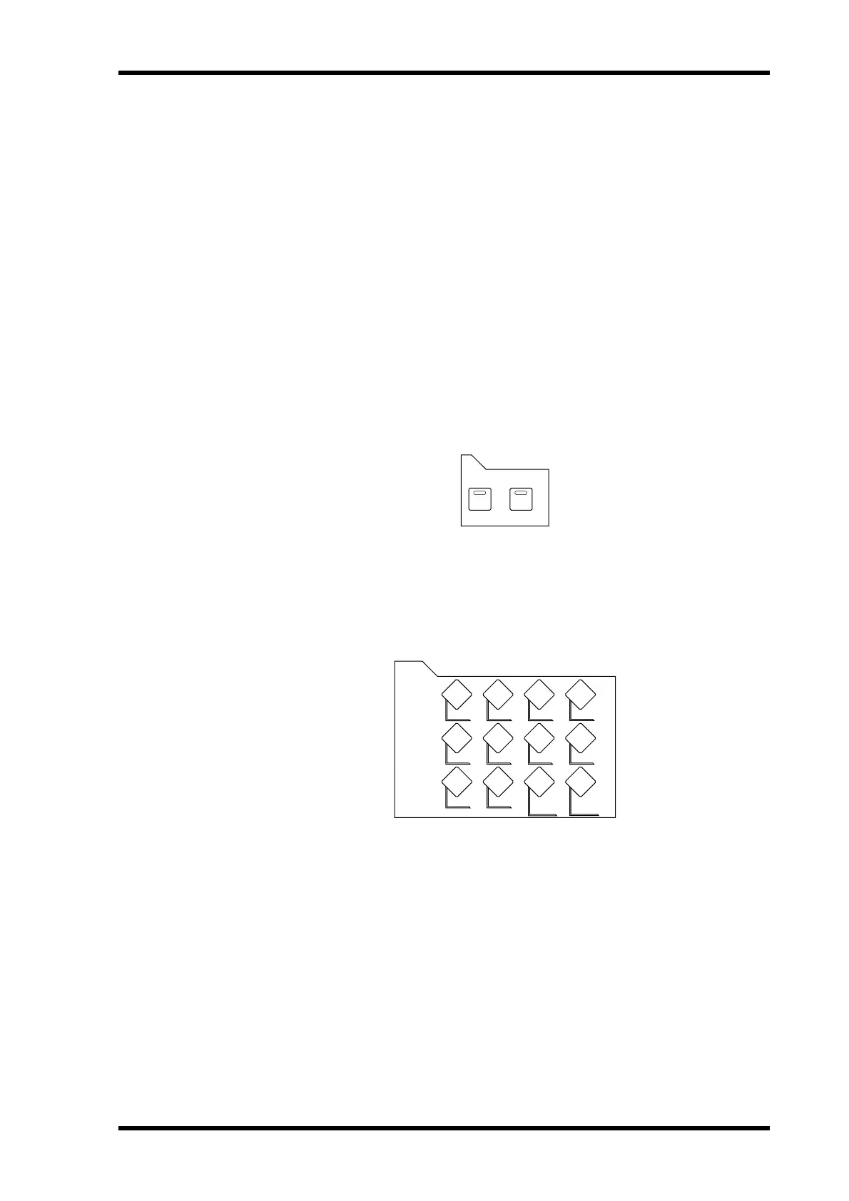
AUX/MTRXFADER
FADER MODE
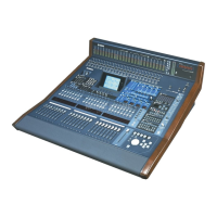
METER
DISPLAY ACCESS