Analog Input Spec 347
DM2000—Owner’s Manual
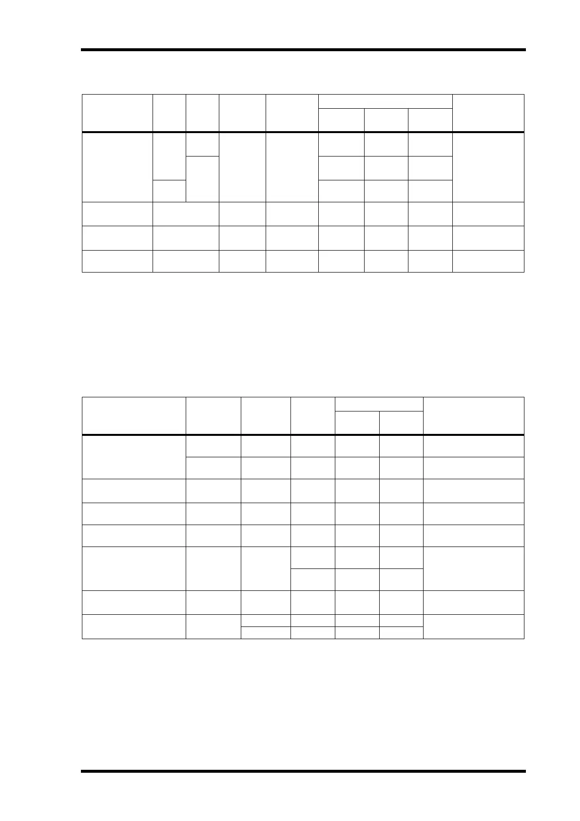
Analog Input Spec
In these specifications, when dB represents a specific voltage, 0 dB is referenced to 0.775 Vrms.
For 2TR IN ANALOG 2 levels, 0 dBV is referenced to 1.00 Vrms.
All input AD converters (except INSERT IN 1–24) are 24-bit linear, 128-times oversampling.
+48 V DC (phantom power) is supplied to CH INPUT (1–24) XLR type connectors via individual switches.
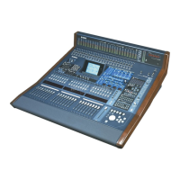
Analog Output Spec
STEREO OUT [L, R], 0 dBV is referenced to 1.00 Vrms.
In these specifications, when dB represents a specific voltage, 0 dB is referenced to 0.775 Vrms.
All output DA converters (except INSERT OUT 1–24) are 24-bit, 128-times oversampling.
Input PAD GAIN
Actual Load
Impedance
For Use With
Nominal
Input level
Connector
Sensitivity
1
1. Sensitivity is the lowest level that will produce an output of +4 dB (1.23 V) or the nominal output level when the unit
is set to maximum gain. (All faders and level controls are maximum position.)
Nominal
Max.
before clip
INPUT A/B 1–24
0
–60 dB
3k Ω
50–600 Ω
Mics & 600 Ω
Lines
–70 dB
(0.245 mV)
–60 dB
(0.775 mV)
–46 dB
(3.88 mV)
A: XLR-3-31 type
(Balanced)
2
2. XLR-3-31 type connectors are balanced (1=GND, 2=HOT, 3=COLD).
–16 dB
–26 dB
(38.8 mV)
–16 dB
(0.123 V)
–2 dB
(616 mV)
B: Phone jack (TRS)
(Balanced)
3
3. Phone jacks are balanced (Tip=HOT, Ring=COLD, Sleeve=GND).
26
0dB
(775 mV)
+10 dB
(2.45 V)
+24 dB
(12.28 V)
INSERT IN 1–24 — 10K Ω 600 Ω Lines
–6dB
(388 mV)
+4 dB
(1.23 V)
+18 dB
(6.16 V)
Phone jack (TRS)
(Balanced)
3
2TR IN ANALOG 1
[L, R]
— 10K Ω 600 Ω Lines
+4 dB
(1.23 V)
+4 dB
(1.23 V)
+18 dB
(6.16 V)
Phone jack (TRS)
(Balanced)
3
2TR IN ANALOG 2
[L, R]
— 10K Ω 600 Ω Lines
–10 dBV
(0.316 V)
–10 dBV
(0.316 V)
+4 dBV
(1.58 V)
Phono
(Unbalanced)
Output
Actual Source
Impedance
For Use
With
Nominal
GAIN SW
1
1. The maximum output level of each OMNI OUT can be set internally.
Output level
Connector
Nominal
Max.
before clip
STEREO OUT [L, R]
600 Ω 10k Ω Lines —
–10 dBV
(0.316 V)
+4 dBV
(1.58 V)
Phono (Unbalanced)
150 Ω 600 Ω Lines —
+4 dB
(1.23 V)
+18 dB
(6.16 V)
XLR-3-32 type (Balanced)
2
2. XLR-3-32 type connectors are balanced (1=GND, 2=HOT, 3=COLD).
STUDIO MONITOR OUT
[L, R]
150 Ω 10k Ω Lines —
+4 dB
(1.23 V)
+18 dB
(6.16 V)
Phone Jack (TRS)
(Balanced)
3
3. Phone jacks are balanced (Tip=HOT, Ring=COLD, Sleeve=GND).
C-R MONITOR OUT LARGE
[L, R]
150 Ω 600 Ω Lines —
+4 dB
(1.23 V)
+18 dB
(6.16 V)
XLR-3-32 type (Balanced)
2
C-R MONITOR OUT SMALL
[L, R]
150 Ω 600 Ω Lines —
+4 dB
(1.23 V)
+18 dB
(6.16 V)
XLR-3-32 type (Balanced)
2
OMNI OUT 1–8 150 Ω 10k Ω Lines
+18 dB
(default)
+4 dB
(1.23 V)
+18 dB
(6.16 V)
Phone Jack (TRS)
(Balanced)
3
+4 dB
–10 dB
(0.245 V)
+4 dB
(1.23 V)
INSERT OUT 1–24 150 Ω 10k Ω Lines —
+4 dB
(1.23 V)
+18 dB
(6.16 V)
Phone Jack (TRS)
(Balanced)
3
PHONES 100 Ω
8 Ω Phones — 4 mW 25 mW
Stereo Phone Jack (TRS)
(Unbalanced)
4
4. PHONES stereo phone jack is unbalanced (Tip=LEFT, Ring=RIGHT, Sleeve=GND).
40 Ω Phones — 12 mW 75 mW