336 Appendix A: Parameter Lists
DM2000—Owner’s Manual
Dynamics Parameters
The dynamics effects for each channel strip include a Gate section (only for Input Chan-
nels) and a Comp section. The Gate section includes Gate and Ducking types. The Comp
section includes Compressor, Expander, Compander Hard (COMP. (H)), and Compander
Soft (COMP. (S)) types.
GATE Section (Only for Input Channels)
GATE
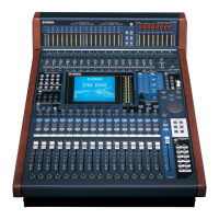
A gate attenuates signals below a set THRESHOLD level by a specified amount (RANGE).
Parameter Range Description
THRESHOLD (dB) –54.0 to 0.0 (541 points)
This determines the level at which the gate effect
is applied.
RANGE (dB) –70 to 0 (71 points)
This determines the amount of attenuation when
the gate closes.
ATTACK (ms) 0–120 (121 points)
This determines how fast the gate opens when the
signal exceeds the threshold level.
HOLD (ms)
44.1kHz: 0.02 ms – 2.13 sec
48kHz: 0.02 ms – 1.96 sec
88.2kHz: 0.01 ms – 1.06 sec
96kHz: 0.01 ms – 981 ms
(160 points)
This determines how long the gate stays open
once the trigger signal has fallen below the thresh-
old.
DECAY (ms)
44.1kHz: 6 ms – 46.0 sec
48kHz: 5 ms – 42.3 sec
88.2kHz: 3 ms – 23.0 sec
96kHz: 3 ms – 21.1 sec
(160 points)
This determines how fast the gate closes once the
hold time has expired. The value is expressed as
the duration required for the level to change by
6 dB.
Input Level Time Time
Output Level
Input Level
Output Level
I/O Characteristics Time Series Analysis
RANGE
THRESHOLD
THRESHOLD
RANGE
Input Signal Output Signal
AT TACK DECAY
HOLD