GENERATOR
5-40
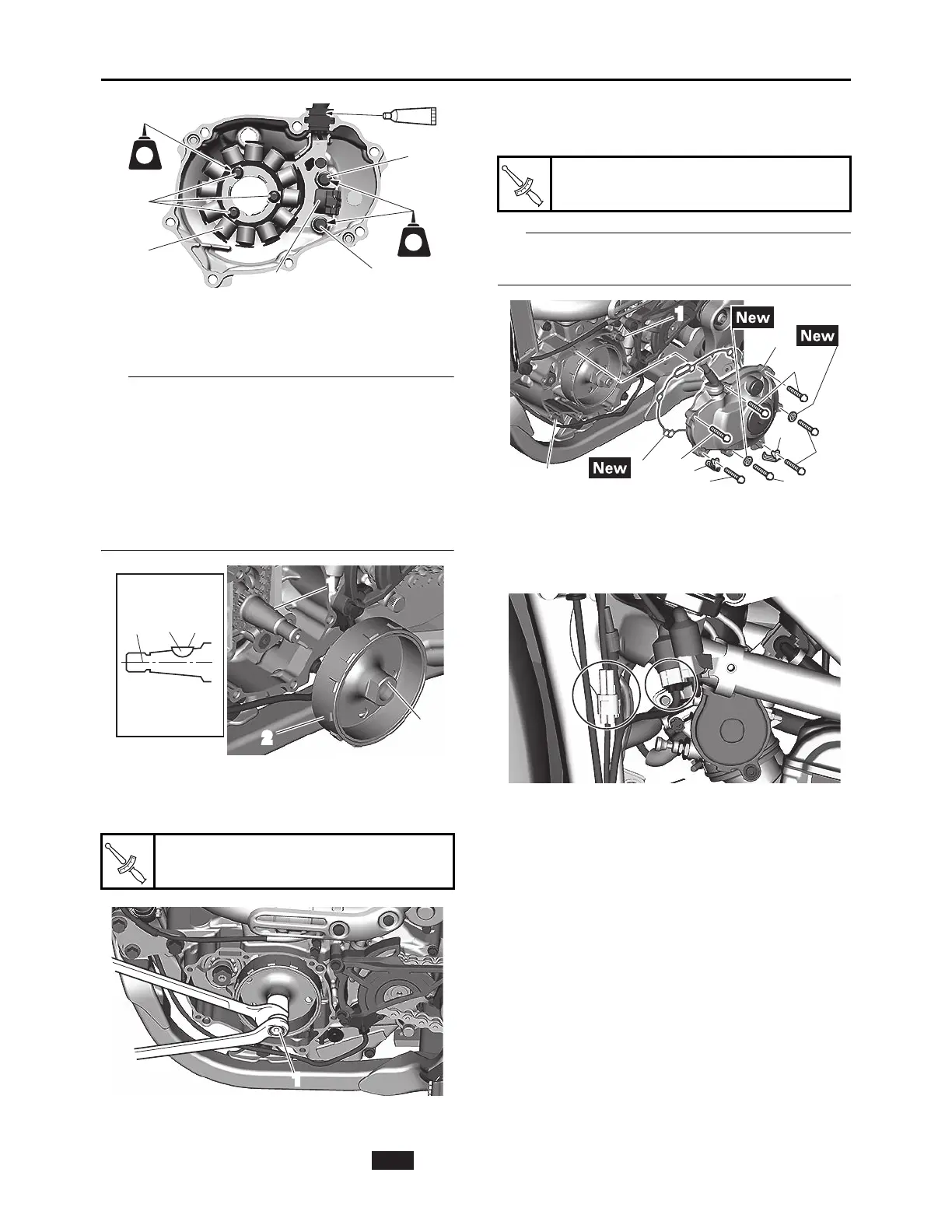
2. Install:
• Woodruff key “1”
• Generator rotor “2”
• Clean the contact surfaces of the tapered por-
tions of the crankshaft and generator rotor.
• When installing the woodruff key, make sure
that its flat surface “a” is in parallel with the
crankshaft center line “b”.
• When installing the generator rotor, align the
keyway “c” of the generator rotor with the
woodruff key.
3. Install:
• Washer
• Nut (generator rotor) “1”
4. Install:
• Dowel pin “1”
• Gasket (left crankcase cover) “2”
• Crankcase cover (left) “3”
• Lead holder “4”
• Bolt (left crankcase cover) “5”
Tighten the bolts in stages and in a crisscross
pattern.
5. Connect:
• Stator coil assembly lead
Refer to “CABLE ROUTING DIAGRAM” on
page 2-17.
Nut (generator rotor)
65 N·m (6.5 kgf·m, 48 lb·ft)
LT
LT
2
4
3
4
1
b1
a
c
1
2
1
New
Bolt (left crankcase cover)
10 N·m (1.0 kgf·m, 7.4 lb·ft)
1
1
2
3
5
5
5
5
5
4
4