ELECTRICAL COMPONENTS
8-59
EAM30357
CHECKING THE BULBS AND BULB
SOCKETS
1. Remove:
• Bulb
ECA25930
Be sure to hold the socket firmly when re-
moving the bulb. Never pull the lead, other-
wise it may be pulled out of the terminal in
the coupler.
Bulbs “a” is used for warning light and can be re-
moved from their respective socket by carefully
pulling them out.
2. Check:
• Bulb (for continuity)
(with the digital circuit tester)
No continuity Replace.
Before checking for continuity, set the digital cir-
cuit tester to “” range.
3. Check:
• Bulb socket (for continuity)
(with the digital circuit tester)
No continuity Replace.
Check each bulb socket for continuity in the
same manner as described in the bulb section;
however, note the following.
a. Install a good bulb into the bulb socket.
b. Connect the digital circuit tester probes to
the respective leads of the bulb socket.
c. Check the bulb socket for continuity. If any
of the readings indicate no continuity, re-
place the bulb socket.
EAM30290
CHECKING THE FUSES
The following procedure applies to all of the fus-
es.
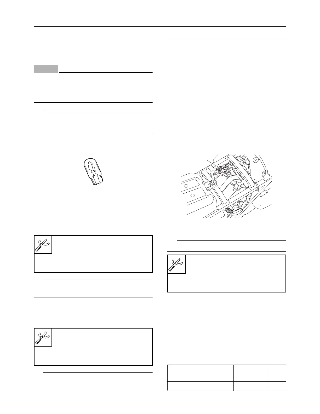
1. Remove:
• Seat
Refer to “GENERAL CHASSIS” on page 4-1.
2. Check:
• Main fuse “1”
• Radiator fan motor fuse “2”
a. Connect the digital circuit tester to the fuse
and check the continuity.
Set the digital circuit tester selector to “”.
b. If the digital circuit tester indicates “O.L”,
replace the fuse.
3. Replace:
• Fuse
a. Install a new fuse of the correct amperage
rating.
b. Push the start switch to verify if the electri-
cal circuit is operational.
c. If the fuse immediately blows again, check
the electrical circuit.
Digital circuit tester (CD732)
90890-03243
Model 88 Multimeter with tachom-
eter
YU-A1927
Digital circuit tester (CD732)
90890-03243
Model 88 Multimeter with tachom-
eter
YU-A1927
Digital circuit tester (CD732)
90890-03243
Model 88 Multimeter with tachom-
eter
YU-A1927
Fuses
Amperage
rating
Q’ty
Main 15 A 1
1
2