ELECTRICAL COMPONENTS
8-58
Check each switch for continuity with the digital circuit tester. If the continuity reading is incorrect, check
the wiring connections and if necessary, replace the switch.
ECA14371
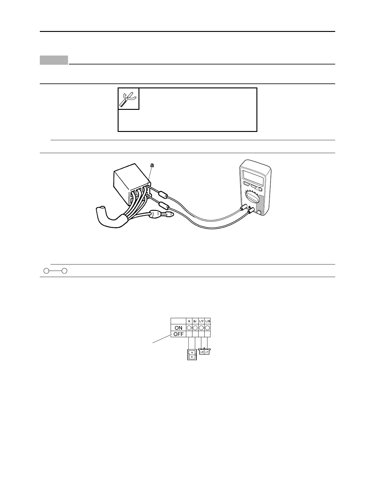
Never insert the tester probes into the coupler terminal slots. Always insert the probes from the
opposite end “a” of the coupler, taking care not to loosen or damage the leads.
When checking for continuity, switch back and forth between the switch positions a few times.
Terminal connections of the switch are shown in the terminal connection diagram below.
The switch positions “a” are shown in the far left column and the switch lead colors are shown in the
top row in the switch illustration.
“ ” indicates continuity between switch terminals (i.e., a closed circuit at each switch position).
The example illustration below shows that:
There is continuity between red and brown when the switch is “ON”.
Digital circuit tester (CD732)
90890-03243
Model 88 Multimeter with tachom-
eter
YU-A1927