SHIFT SHAFT
5-58
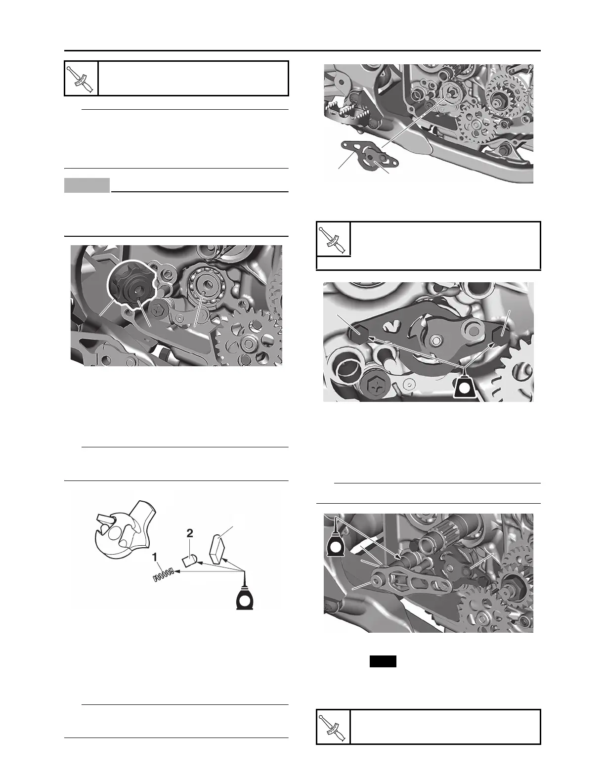
• Align the notch “a” on the segment with the pin
“b” on the shift cam.
• With the stopper lever pushed down, install the
segment.
ECA24680
If the segment gets an impact, the stopper le-
ver may be damaged. Take care not to give
an impact to it when tightening the bolt.
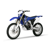
3. Install:
• Spring “1”
• Pawl pin “2”
• Pawl “3”
(to the shift lever)
Apply the engine oil on the spring, pawl pin and
pawl.
4. Install:
• Shift lever assembly
(to the shift guide)
5. Install:
• Shift lever assembly “1”
• Shift guide “2”
The shift lever assembly is installed at the same
time as the shift guide.
6. Tighten:
• Shift guide bolt “1”
7. Install:
• Roller “1”
• Shift shaft spring “2” (to the shift shaft)
• Collar “3” (to the shift shaft)
• Shift shaft “4”
Apply the engine oil on the shift shaft.
8. Install:
• Oil seal
9. Install:
• Shift pedal “1”
• Shift pedal bolt “2”
Segment bolt
30 N·m (3.0 kgf·m, 22 lb·ft)
1
1
a
b
1
1
2
3
E
Shift guide bolt
10 N·m (1.0 kgf·m, 7.4 lb·ft)
LOCTITE®
Shift pedal bolt
12 N·m (1.2 kgf·m, 8.9 lb·ft)
1
2
LT
1
1
1
1
1
2
3
4
E