ENGINE
3-8
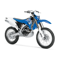
5. Adjust:
• Valve clearance
a. Remove the camshaft (intake and ex-
haust).
Refer to “CAMSHAFT” on page 5-14.
b. Remove the valve lifter “2” and the adjust-
ing pad “3” with a valve lapper “1”.
• Place a cloth in the timing chain space to pre-
vent adjusting pads from falling into the crank-
case.
• Identity each valve lifter and adjusting pad po-
sition very carefully so that they can be rein-
stalled in their original place.
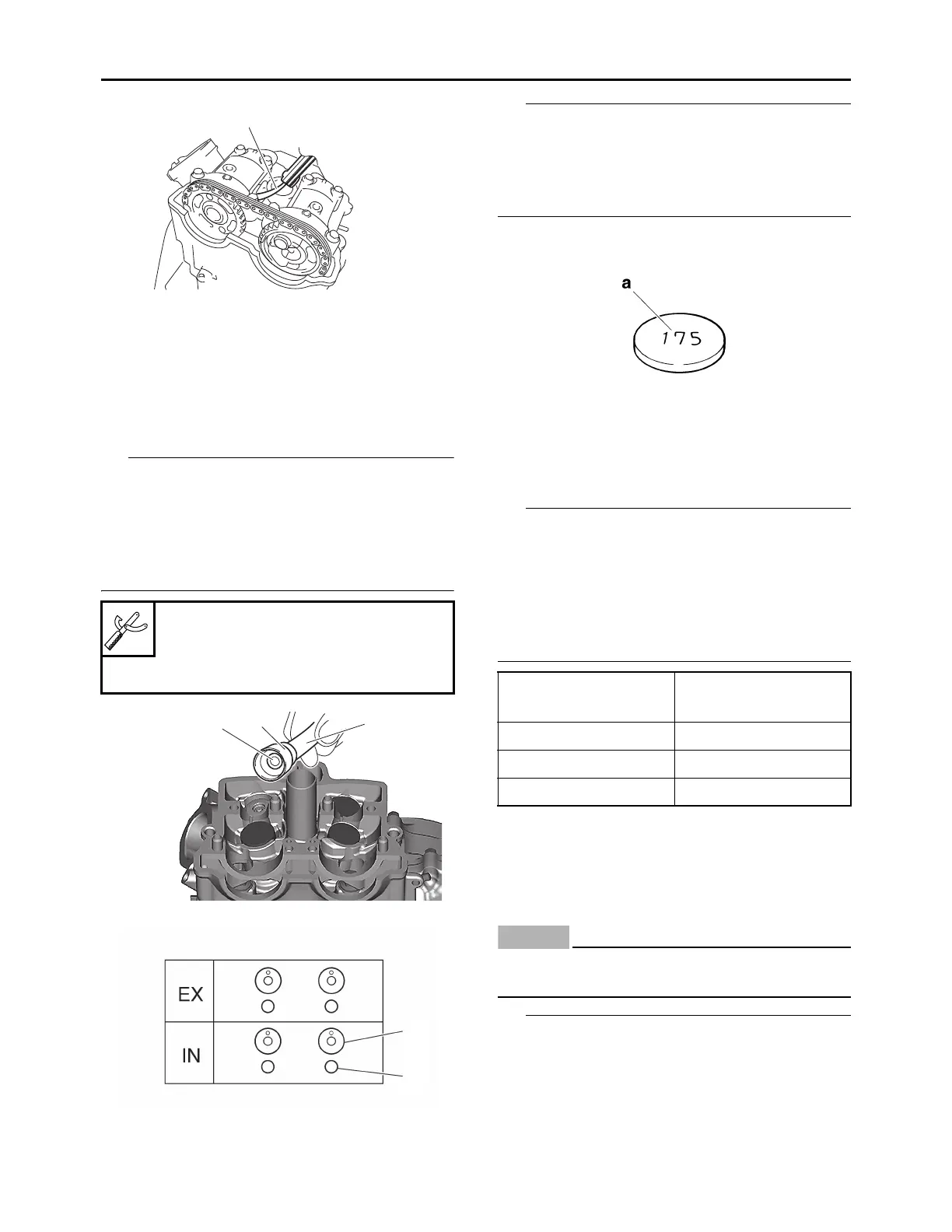
c. Check the number on the originally in-
stalled adjusting pad.
• The adjusting pad number “a” is indicated on
the top of the adjusting pad.
• For the number on the originally installed ad-
justing pad, convert the last digit of adjusting
pad number as per the below table.
d. Select an adjusting pad with a proper
valve clearance from the adjusting pad se-
lection table.
• There are 25 types of adjusting pads, ranging
from 1.20 mm (0.0472 in) to 2.40 mm (0.0945
in), in increments of 0.05 mm (0.0020 in).
• The field where the number on the originally in-
stalled adjusting pad and the measured valve
clearance intersect shows the adjusting pad
number to replace.
Example:
Pad number = 148
Rounded value = 150
e. Install the new adjusting pads “4” and the
valve lifters “5”.
ECA24310
Do not twist adjusting pads and valve lifters
forcibly during installation.
• Apply the engine oil on the valve lifters.
• Apply molybdenum disulfide oil to the valve
stem ends.
• Check that the valve lifters turn smoothly when
rotated with your finger.
• Make sure that valve lifters and adjusting pads
are installed in place.
Valve lapper (ø14)
90890-04101
Valve lapper (ø14)
YM-A8998
1
1
3
2
2
3
Last digit of pad num-
ber
Rounded value
0, 1 or 2 0
4, 5 or 6 5
8 or 9 10